Pinout and connectors, Serial ports, Figure 2- de-9 (db-9) connector pin-out – B&B Electronics APXN-Q5428 - User Manual User Manual
Page 12: Table 1, Serial port pin definition, 0 pinout and connectors, 1 serial ports
B&B Electronics, Inc.
AirborneM2M™ User Manual
12
1/9/2014
5.0
Pinout and Connectors
The following defines the pinouts for the wired interfaces.
5.1
Serial Ports
The AirborneM2M
™ unit supports two serial ports. The Port pinout can change
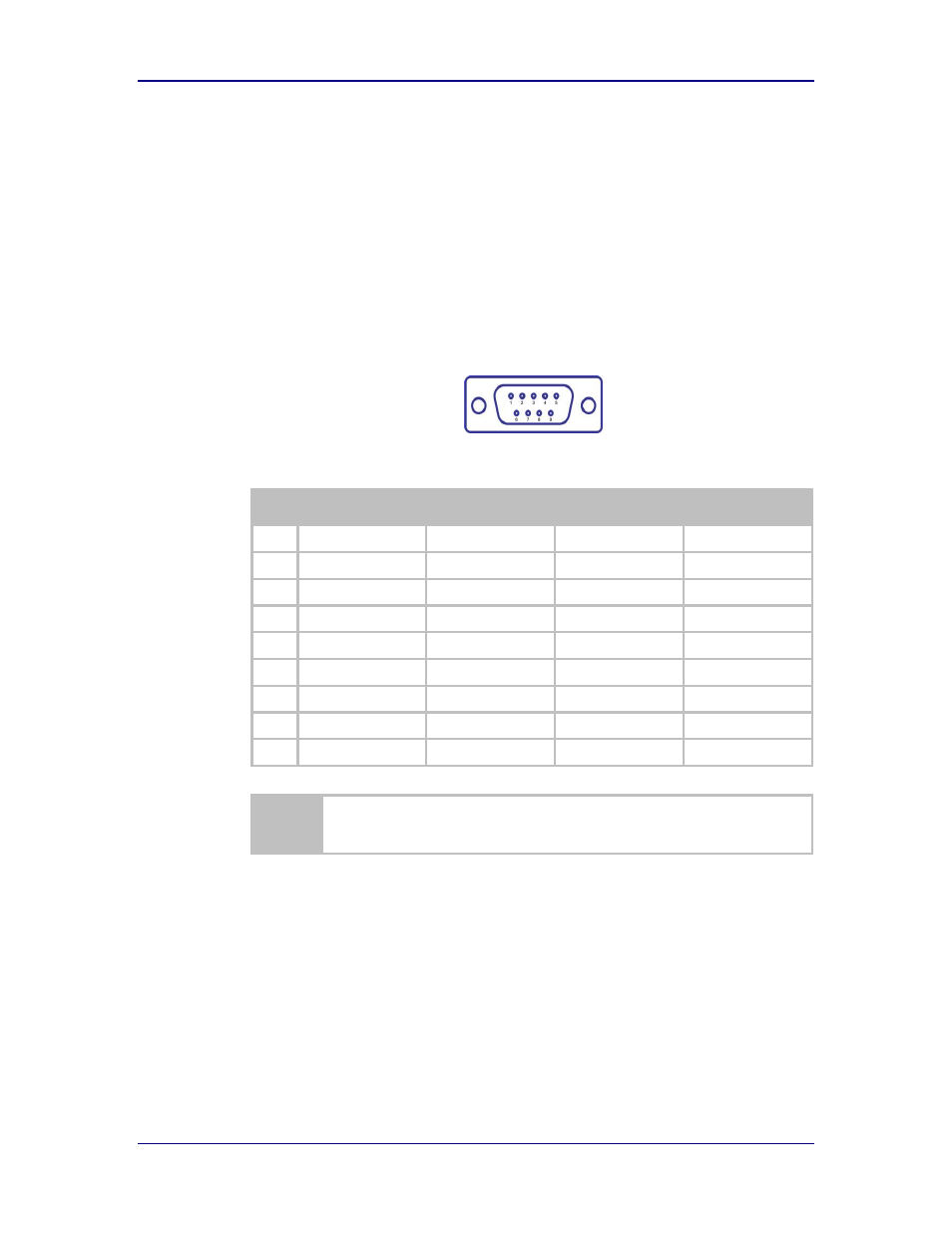
depending upon the interface configuration chosen. Table 1 shows the pinout for
the interface selected.
Figure 2- DE-9 (DB-9) Connector Pin-out
Table 1–Serial Port Pin Definition
Pin
RS232 (DTE)
RS232
w/Power
on pin 9
2
RS422/RS485
4-wire
RS485
2-wire
1
No Connect
No Connect
No Connect
No Connect
2
RxD
RxD
RxD+
Connect to pin 3
3
3
TxD
TxD
TxD+
TxD+/RxD+
4
No Connect
No Connect
No Connect
No Connect
5
GND
GND
GND
GND
6
No Connect
No Connect
RxD-
Connect to pin 9
3
7
RTS
RTS
No Connect
No Connect
8
CTS
CTS
No Connect
No Connect
9
No Connect
5VDC (Input)
TxD-
TxD-/RxD-
1. For 2-wire operation, the user must externally connect pin 3 to pin 2 and
pin 6 to pin 9.
The Port 1 and Port 2 interfaces support the following configurations:
BAUD: 300, 600, 1200, 2400, 4800, 9600, 14400, 19200, 28800, 38400,
57600, 115200, 230400, 460800, 921600
Flow Control: None, Hardware (CTS/RTS), Software (XON/XOFF)
Port 1 Default settings: 9600, 8, N, 1, No Flow Control.
Port 2 Default settings: 9600, 8, N, 1, No Flow Control.