Rainbow Electronics DS2172 User Manual
Page 8
DS2172
031197 8/20
PT3 PTR.3
Polynomial Tap Bit 3.
PT2 PTR.2
Polynomial Tap Bit 2.
PT1 PTR.1
Polynomial Tap Bit 1.
PT0 PTR.0
Polynomial Tap Bit 0.
6.0 PATTERN CONTROL REGISTER
The Pattern Control Register (PCR) is used to configure
the operating parameters of the DS2172 and to control
the patterns being generated and received. Also the
PCR is used to control the pattern synchronizer and the
error and bit counters.
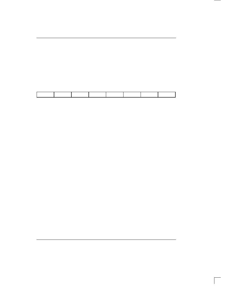
PCR: PATTERN CONTROL REGISTER (Address=06 Hex)
(MSB)
(LSB)
TL
QRSS
PS
LC
RL
SYNCE
RESYNC
LPBK
SYMBOL
POSITION
NAME AND DESCRIPTION
TL
PCR.7
Transmit Load. A low to high transition loads the pattern generator with
the contents of the Pattern Set Registers. PCR.7 is logically ORed with the
input pin TL. Must be cleared and set again for subsequent loads.
QRSS
PCR.6
Zero Suppression Select. Forces a “one” into the pattern whenever the
next 14 bit positions are all “zeros”. Should only be set when using the
QRSS pattern.
0 = Zero suppression disabled
1 = Zero suppression enabled
PS
PCR.5
Pattern Select.
0 = Repetitive Pattern
1 = Pseudorandom Pattern
LC
PCR.4
Latch Count Registers. A low to high transition latches the bit and error
counts into the user accessible registers BCR and BECR and clears the
internal register count. PCR.4 is logically OR’ed with input pin LC. Must be
cleared and set again for subsequent loads.
RL
PCR.3
Receive Data Load. A transition from low to high loads the previous 32 bits
of data received at RDATA into the Pattern Receive Registers (PRR).
PCR.3 is logically OR’ed with input pin RL. Must be cleared and set again
for subsequent latches.
SYNCE
PCR.2
SYNC Enable.
0 = auto resync is enabled.
1 = auto resync is disabled.
RESYNC
PCR.1
Initiate Manual Resync Process. A low to high transition will force the
DS2172 to resynchronize to the incoming pattern at RDATA. Must be
cleared and set again for a subsequent resync.
LPBK
PCR.0
Transmit/Receive Loopback Select. When enabled, the RDATA input is
disabled; TDATA continues to output data as normal. See Figure 1.
0 = loopback disabled
1 = loopback enabled