Electrical characteristics (continued) – Rainbow Electronics MAX5965B User Manual
Page 7
MAX5965A/MAX5965B
High-Power, Quad, Monolithic, PSE Controllers
for Power over Ethernet
_______________________________________________________________________________________
7
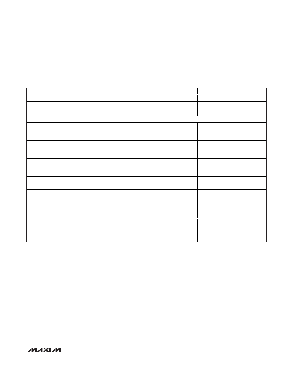
ELECTRICAL CHARACTERISTICS (continued)
(V
AGND
= 32V to 60V, V
EE
= 0V, V
DD
to V
DGND
= +3.3V, all voltages are referenced to V
EE
, unless otherwise noted. Typical values are at
V
AGND
= +48V, V
DGND
= +48V, V
DD
= (V
DGND
+ 3.3V), T
A
= +25°C. Currents are positive when entering the pin and negative other-
wise.) (Note 2)
PARAMETER
SYMBOL
CONDITIONS
MIN
TYP
MAX
UNITS
Differential Nonlinearity
DNL
0.2
1.5
LSB
Gain Error
3
%
ADC Absolute Accuracy
V
SENSE
= 300mV
295
300
305
LSB
TIMING CHARACTERISTICS (For 2-Wire Fast Mode)
Serial-Clock Frequency
f
SCL
400
kHz
Bus Free Time Between a
STOP and START Condition
t
BUF
1.2
µs
Hold Time for a START
Condition
t
HD, STA
0.6
µs
Low Period of the SCL Clock
t
LOW
1.2
µs
High Period of the SCL Clock
t
HIGH
0.6
µs
Setup Time for a Repeated
START Condition (Sr)
t
SU, STA
0.6
µs
Data Hold Time
t
HD, DAT
100
300
ns
Data in Setup Time
t
SU, DAT
100
ns
Rise Time of Both SDA and
SCL Signals, Receiving
t
R
20 +
0.1C
B
300
ns
Fall Time of SDA Transmitting
t
F
20 +
0.1C
B
300
ns
Setup Time for STOP Condition
t
SU, STO
0.6
µs
Capacitive Load for Each Bus
Line
C
B
400
pF
Pulse Width of Spike
Suppressed
t
SP
50
ns
Note 2:
Limits to T
A
= -40°C are guaranteed by design.
Note 3:
Default values. The charge/discharge currents are programmable through the serial interface (see the
Register Map and
Description section).
Note 4:
Default values. The current-limit thresholds are programmed through the I
2
C-compatible serial interface (see the
Register
Map and Description section).
Note 5:
Functional test is performed over thermal shutdown entering test mode.
Note 6:
This is the default value. Threshold can be programmed through serial interface R23h[2:0].
Note 7:
AC disconnect works only if (V
DD
- V
DGND
) ≥ 3V and DGND is connected to AGND.
Note 8:
t
DISC
can also be programmed through the serial interface (R16H) (see the
Register Map and Description section).
Note 9:
R
D
= (V
OUT_2
- V
OUT_1
)/(I
DET_2
- I
DET_1
). V
OUT_1
, V
OUT_2
, I
DET_2
, and I
DET_1
represent the voltage at OUT_ and the cur-
rent at DET_ during phase 1 and 2 of the detection.
Note 10: Default values. The startup and fault times can also be programmed through the I
2
C serial interface (see the
Register Map
and Description section).