Pin description (continued) – Rainbow Electronics MAX5965B User Manual
Page 13
MAX5965A/MAX5965B
High-Power, Quad, Monolithic, PSE Controllers
for Power over Ethernet
______________________________________________________________________________________
13
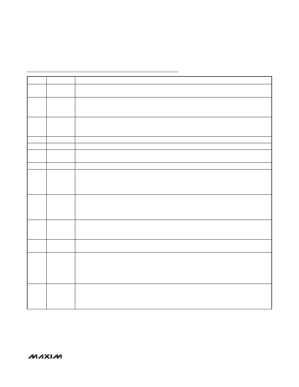
Pin Description (continued)
PIN
NAME
FUNCTION
6
SDAIN
Serial Interface Input Data Line. Connect the data line optocoupler output to SDAIN (see the Typical
Operating Circuits). Connect SDAIN to SDAOUT if using a 2-wire, I
2
C-compatible system.
7–10
A3–A0
Address Bits. A3–A0 form the lower part of the device’s address. Address inputs default high with an
internal 50k
Ω pullup resistor to V
DD
. The address values latch when V
DD
or V
EE
ramps up and exceeds
its UVLO threshold or after a reset. The 3 MSBs of the address are set to 010.
11–14
DET1–DET4
Detection/Classification Voltage Outputs. Use DET1 to set the detection and classification probe voltages
on port 1. Use DET1 for the AC voltage sensing of port 1 when using the AC disconnect scheme (see the
Typical Operating Circuits).
15
DGND
Digital Ground. Connect to digital ground.
16
V
DD
Positive Digital Supply. Connect to a digital power supply (reference to DGND).
17– 20
SHD1–SHD4
Port Shutdown Inputs. Pull
SHD_ low to turn off the external FET on port_. Internally pulled up to V
DD
with
a 50k
Ω resistor.
21
AGND
Analog Ground. Connect to the high-side analog supply.
22, 25,
29, 32
SENSE4,
SENSE3,
SENSE2,
SENSE1
MOSFET Source Current-Sense Negative Inputs. Connect to the source of the power MOSFET and
connect a current-sense resistor between SENSE_ and V
EE
(see the Typical Operating Circuits).
23, 26,
30, 33
GATE4,
GATE3,
GATE2,
GATE1
Port_ MOSFET Gate Drivers. Connect GATE_ to the gate of the external MOSFET (see the Typical
Operating Circuits).
24, 27,
31, 34
OUT4, OUT3,
OUT2, OUT1
MOSFET Drain-Output Voltage Senses. Connect OUT_ to the power MOSFET drain through a resistor
(100
Ω to 100kΩ). The low leakage at OUT_ limits the drop across the resistor to less than 100mV (see the
Typical Operating Circuits).
28
V
EE
Low-Side Analog Supply Input. Connect the low-side analog supply to V
EE
(-48V). Bypass with a 1µF
capacitor between AGND and V
EE
.
35
AUTO
Auto or Shutdown Mode Input. Force AUTO high to enter auto mode after a reset or power-up. Drive low
to put the MAX5965A/MAX5965B into shutdown mode. In shutdown mode, software controls the
operational modes of the MAX5965A/MAX5965B. A 50k
Ω internal pulldown resistor defaults to AUTO low.
AUTO latches when V
DD
or V
EE
ramps up and exceeds its UVLO threshold or when the device resets.
Software commands can take the MAX5965A/MAX5965B out of AUTO while AUTO is high.
36
OSC
Oscillator Input. AC-disconnect detection function uses OSC. Connect a 100Hz ±10%, 2V
P-P
±5%, +1.2V
offset sine wave to OSC. If the oscillator positive peak falls below the OSC_FAIL threshold of 2V, the ports
that have the AC function enabled shut down and are not allowed to power-up. When not using the AC-
disconnect detection function, leave OSC unconnected.