Typical operating characteristics (continued), Pin description – Rainbow Electronics MAX5965B User Manual
Page 12
MAX5965A/MAX5965B
High-Power, Quad, Monolithic, PSE Controllers
for Power over Ethernet
12
______________________________________________________________________________________
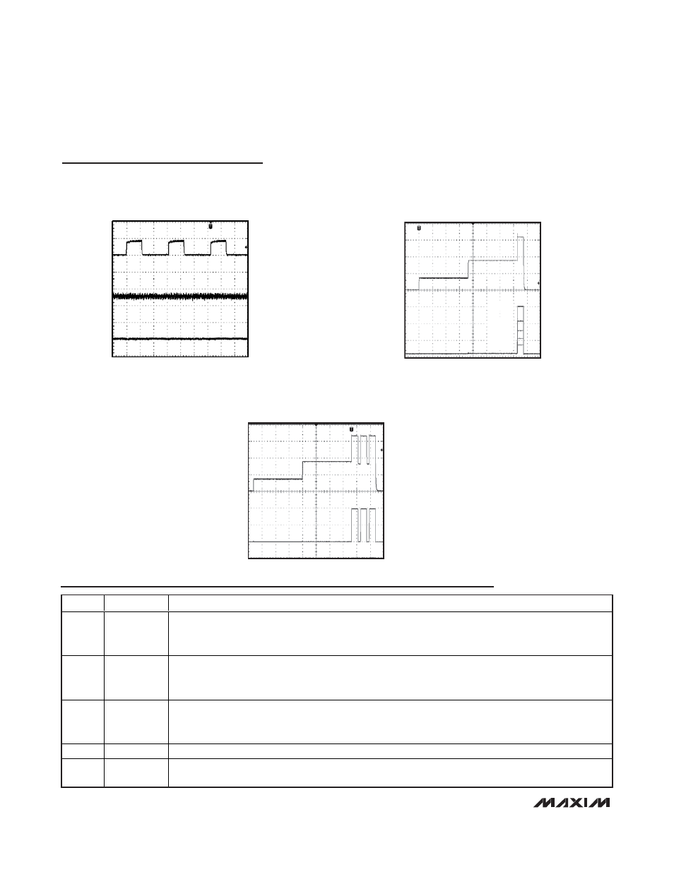
DETECTION WITH INVALID PD (OPEN CIRCUIT,
USING TYPICAL OPERATING CIRCUIT 2)
MAX5965A toc28
40ms/div
I
OUT
1mA/div
0A
0V
(AGND - V
OUT
)
5V/div
V
GATE_
10V/div
V
EE
STARTUP WITH DIFFERENT
PD CLASSES
MAX5965A toc29
I
OUT
20mA/div
0V
0A
V
AGND
- V
OUT
5V/div
CLASS 1
CLASS 2
CLASS 3
CLASS 4
CLASS 5
2-EVENT CLASSIFICATION
WITH A CLASS 4 PD
MAX5965A toc30
I
OUT
20mA/div
V
AGND
- V
OUT
5V/div
V
GATE
10V/div
0V
0A
V
EE
Typical Operating Characteristics (continued)
(V
EE
= -48V, V
DD
= +3.3V, V
AUTO
= V
AGND
= V
DGND
= 0V, RESET = SHD_ = unconnected, R
SENSE
= 0.5Ω, IVEE = 00, ICUT = 000,
T
A
= +25°C, all registers = default setting, unless otherwise noted.)
Pin Description
PIN
NAME
FUNCTION
1
RESET
Hardware Reset. Pull RESET low for at least 300µs to reset the device. All internal registers reset to their
default value. The address (A0–A3), and AUTO and MIDSPAN input-logic levels latch on during low-to-
high transition of RESET. RESET is internally pulled up to V
DD
with a 50k
Ω resistor.
2
MIDSPAN
Midspan Mode Input. An internal 50k
Ω pulldown resistor to DGND sets the default mode to endpoint PSE
operation (power-over-signal pairs). Pull MIDSPAN to V
DIG
to set midspan operation. The MIDSPAN value
latches after the device is powered up or reset (see the PD Detection section).
3
INT
Open-Drain Interrupt Output. INT goes low whenever a fault condition exists. Reset the fault condition
using software or by pulling RESET low (see the Interrupt section for more information about interrupt
management).
4
SCL
Serial Interface Clock Line Input
5
SDAOUT
Serial Output Data Line. Connect the data line optocoupler input to SDAOUT (see the Typical Operating
Circuits). Connect SDAOUT to SDAIN if using a 2-wire, I
2
C-compatible system.