Watchdog, Address inputs, C-compatible serial interface – Rainbow Electronics MAX5965B User Manual
Page 23
MAX5965A/MAX5965B
High-Power, Quad, Monolithic, PSE Controllers
for Power over Ethernet
______________________________________________________________________________________
23
Watchdog
The R1Dh, R1Eh, and R1Fh registers control the watch-
dog operation. The watchdog function, when enabled,
allows the MAX5965A/MAX5965B to gracefully take
over control or securely shuts down the power to the
ports in case of software/firmware crashes. Contact the
factory for more details.
Address Inputs
A3, A2, A1, and A0 represent the 4 LSBs of the chip
address. The complete chip address is 7 bits (see
Table 4).
The 4 LSBs latch on the low-to-high transition of RESET or
after a power-supply start (either on V
DD
or V
EE
). Address
inputs default high through an internal 50kΩ pullup resistor
to V
DD
. The MAX5965A/MAX5965B also respond to the
call through a global address 30h (see the
Global
Addressing and Alert Response Protocol
section).
I
2
C-Compatible Serial Interface
The MAX5965A/MAX5965B operate as a slave that
sends and receives data through an I
2
C-compatible, 2-
wire or 3-wire interface. The interface uses a serial-data
input line (SDAIN), a serial-data output line (SDAOUT),
and a serial-clock line (SCL) to achieve bidirectional
communication between master(s) and slave(s). A mas-
ter (typically a microcontroller) initiates all data transfers
to and from the MAX5965A/MAX5965B, and generates
the SCL clock that synchronizes the data transfer. In
most applications, connect the SDAIN and the SDAOUT
lines together to form the serial-data line (SDA).
Using the separate input and output data lines allows
optocoupling with the controller bus when an isolated
supply powers the microcontroller.
The MAX5965A/MAX5965B SDAIN line operates as an
input. The MAX5965A/MAX5965B SDAOUT operates as
an open-drain output. A pullup resistor, typically 4.7kΩ,
is required on SDAOUT. The MAX5965A/MAX5965B SCL
line operates only as an input. A pullup resistor, typically
4.7kΩ, is required on SCL if there are multiple masters,
or if the master in a single-master system has an open-
drain SCL output.
0
1
0
A3
A2
A1
A0
R/W
Table 4. MAX5965A/MAX5965B Address
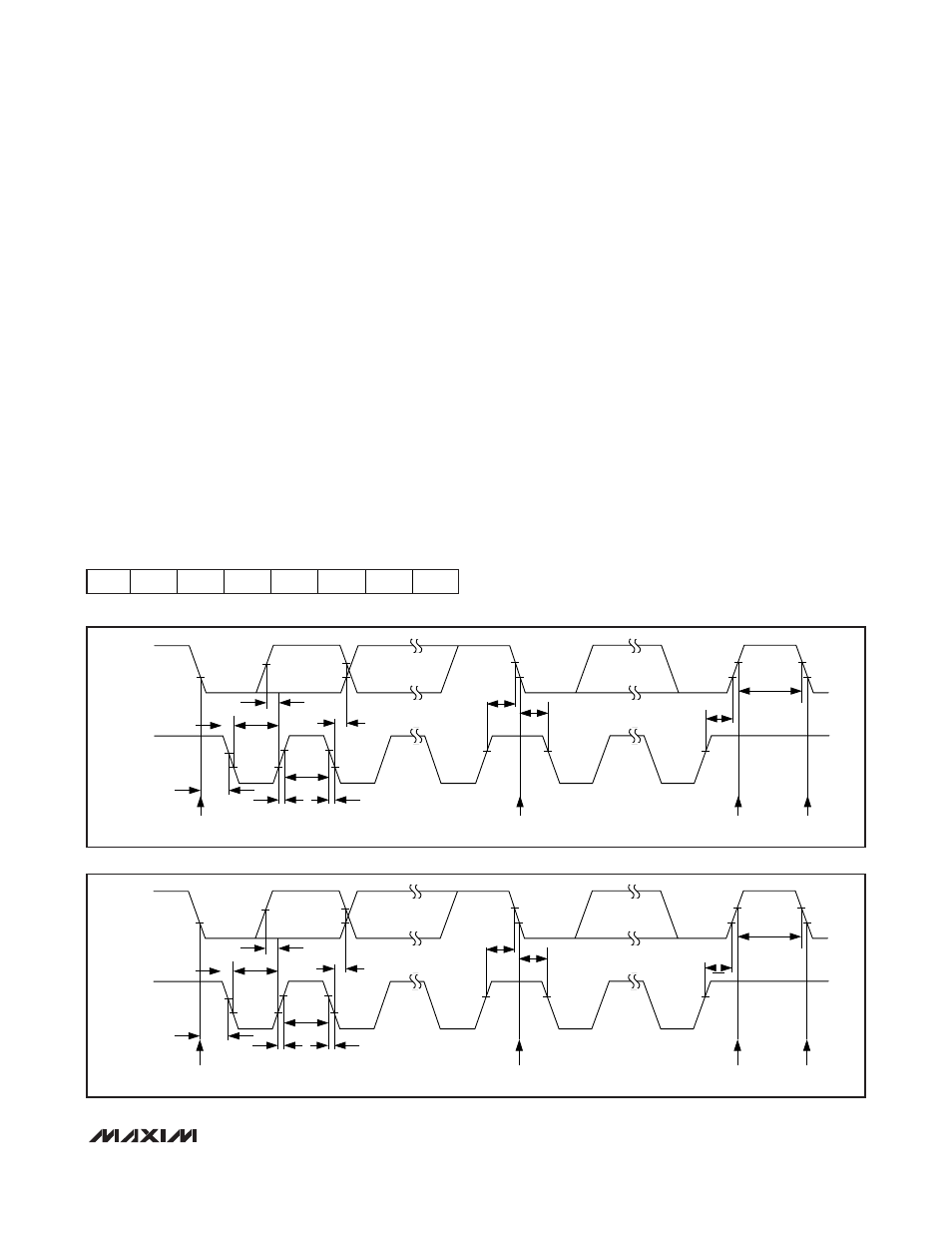
Figure 4. 2-Wire, Serial-Interface Timing Details
SCL
SDAIN
t
LOW
t
HIGH
t
R
t
F
t
BUF
START
CONDITION
STOP
CONDITION
REPEATED START CONDITION
START CONDITION
t
HD, STA
t
SU, DAT
t
HD, DAT
t
SU, STA
t
HD, STA
t
SU, STO
Figure 5. 3-Wire, Serial-Interface Timing Details
SCL
SDAIN/SDA
t
LOW
t
HIGH
t
R
t
F
t
BUF
START
CONDITION
STOP
CONDITION
REPEATED START CONDITION
START CONDITION
t
HD, STA
t
SU, DAT
t
HD, DAT
t
SU, STA
t
HD, STA
t
SU, STO