Rainbow Electronics MAX5965B User Manual
Page 24
MAX5965A/MAX5965B
High-Power, Quad, Monolithic, PSE Controllers
for Power over Ethernet
24
______________________________________________________________________________________
Serial Addressing
Each transmission consists of a START condition (Figure
6) sent by a master, followed by the MAX5965A/
MAX5965B 7-bit slave address plus R/W bit, a register
address byte, one or more data bytes, and finally a
STOP condition.
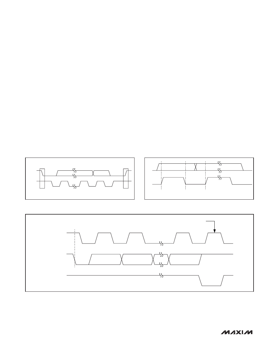
START and STOP Conditions
Both SCL and SDA remain high when the interface is
not busy. A master signals the beginning of a transmis-
sion with a START (S) condition by transitioning SDA
from high to low while SCL is high. When the master fin-
ishes communicating with the slave, the master issues
a STOP (P) condition by transitioning SDA from low to
high while SCL is high. The STOP condition frees the
bus for another transmission.
Bit Transfer
Each clock pulse transfers one data bit (Figure 7). The
data on SDA must remain stable while SCL is high.
Acknowledge
The acknowledge bit is a clocked 9th bit (Figure 8) that
the recipient uses to handshake receipt of each byte of
data. Thus each byte effectively transferred requires 9
bits. The master generates the 9th clock pulse, and the
recipient pulls down SDA (or the SDAOUT in the 3-wire
interface) during the acknowledge clock pulse, so that
the SDA line is stable low during the high period of the
clock pulse. When the master transmits to the
MAX5965A/MAX5965B, the MAX5965A/MAX5965B
generate the acknowledge bit. When the MAX5965A/
MAX5965B transmit to the master, the master gener-
ates the acknowledge bit.
Figure 6. START and STOP Conditions
START
STOP
S
P
SDA/
SDAIN
SCL
Figure 7. Bit Transfer
SDA
SCL
DATA LINE STABLE;
DATA VALID
.
CHANGE OF
DATA ALLOWED
Figure 8. Acknowledge
SCL
SDA
BY TRANSMITTER
CLOCK PULSE FOR ACKNOWLEDGEMENT
START CONDITION
SDA
BY RECEIVER
1
2
8
9
S