Table 14. power status register, Table 15. address input status register – Rainbow Electronics MAX5965B User Manual
Page 32
MAX5965A/MAX5965B
High-Power, Quad, Monolithic, PSE Controllers
for Power over Ethernet
32
______________________________________________________________________________________
PGOOD_ is set to 1 (Table 14) at the end of the power-
up startup period if the power-good condition is met (0
< (V
OUT
- V
EE
) < PG
TH
). The power-good condition
must remain valid for more than t
PGOOD
to assert
PGOOD_. PGOOD_ is reset to 0 whenever the output
falls out of the power-good condition. A fault condition
immediately forces PGOOD_ low.
PWR_EN_ is set to 1 when the port power is turned on.
PWR_EN resets to 0 as soon as the port turns off. Any
transition of PGOOD_ and PWR_EN_ bits set the corre-
sponding bit in the power event registers R02h/R03h
(Table 8). A reset sets R10h = 00h.
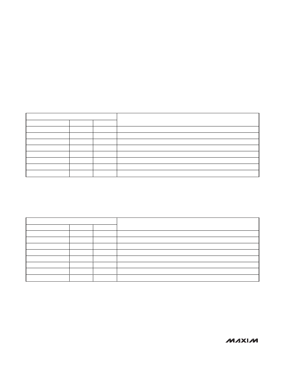
Table 14. Power Status Register
ADDRESS = 10h
SYMBOL
BIT
R/W
DESCRIPTION
PGOOD4
7
R
Power-good condition on port 4
PGOOD3
6
R
Power-good condition on port 3
PGOOD2
5
R
Power-good condition on port 2
PGOOD1
4
R
Power-good condition on port 1
PWR_EN4
3
R
Power is enabled on port 4
PWR_EN3
2
R
Power is enabled on port 3
PWR_EN2
1
R
Power is enabled on port 2
PWR_EN1
0
R
Power is enabled on port 1
Table 15. Address Input Status Register
ADDRESS = 11h
SYMBOL
BIT
R/W
DESCRIPTION
Reserved
7
R
Reserved
Reserved
6
R
Reserved
A3
5
R
Device address, A3 pin latched-in status
A2
4
R
Device address, A2 pin latched-in status
A1
3
R
Device address, A1 pin latched-in status
A0
2
R
Device address, A0 pin latched-in status
MIDSPAN
1
R
MIDSPAN input’s latched-in status
AUTO
0
R
AUTO input’s latched-in status
A3, A2, A1, A0 (Table 15) represent the 4 LSBs of the
MAX5965A/MAX5965B address (Table 4). During a
reset, the device latches into R11h. These 4 bits
address from the corresponding inputs as well as the
state of the MIDSPAN and AUTO inputs. Changes to
those inputs during normal operation are ignored.