Table 16a. operating mode register, Table 16b. operating mode status – Rainbow Electronics MAX5965B User Manual
Page 33
MAX5965A/MAX5965B
High-Power, Quad, Monolithic, PSE Controllers
for Power over Ethernet
______________________________________________________________________________________
33
Setting DCD_EN_ to 1 enables the DC load disconnect
detection feature (Table 17). Setting ACD_EN_ to 1
enables the AC load disconnect feature. If enabled, the
load disconnect detection starts during power mode
and after startup when the corresponding PGOOD_ bit
in register R10h (Table 14) goes high. A reset sets
R13h = 0000AAAA where A represents the latched-in
state of the AUTO input prior to the reset.
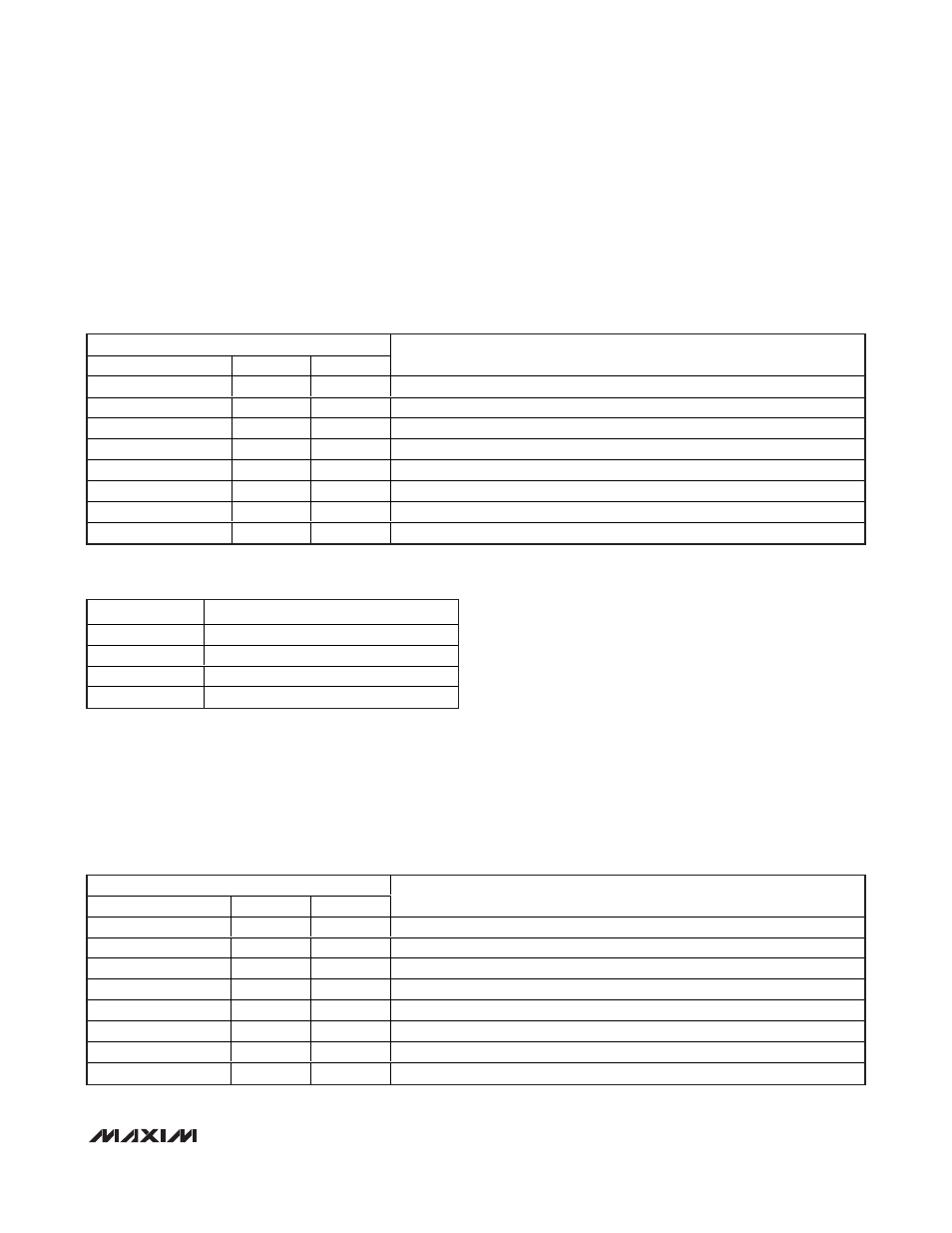
Table 16a. Operating Mode Register
ADDRESS = 12h
SYMBOL
BIT
R/W
DESCRIPTION
P4_M1
7
R/W
MODE[1] for port 4
P4_M0
6
R/W
MODE[0] for port 4
P3_M1
5
R/W
MODE[1] for port 3
P3_M0
4
R/W
MODE[0] for port 3
P2_M1
3
R/W
MODE[1] for port 2
P2_M0
2
R/W
MODE[0] for port 2
P1_M1
1
R/W
MODE[1] for port 1
P1_M0
0
R/W
MODE[0] for port 1
Table 17. Load Disconnect Detection Enable Register
ADDRESS = 13h
SYMBOL
BIT
R/W
DESCRIPTION
ACD_EN4
7
R/W
Enable AC disconnect detection on port 4
ACD_EN3
6
R/W
Enable AC disconnect detection on port 3
ACD_EN2
5
R/W
Enable AC disconnect detection on port 2
ACD_EN1
4
R/W
Enable AC disconnect detection on port 1
DCD_EN4
3
R/W
Enable DC disconnect detection on port 4
DCD_EN3
2
R/W
Enable DC disconnect detection on port 3
DCD_EN2
1
R/W
Enable DC disconnect detection on port 2
DCD_EN1
0
R/W
Enable DC disconnect detection on port 1
Table 16b. Operating Mode Status
MODE
DESCRIPTION
00
Shutdown
01
Manual
10
Semi-auto
11
Auto
The MAX5965A/MAX5965B use 2 bits for each port to
set the mode of operation. Set the modes according to
Table 16a and 16b.
A reset sets R12h = AAAAAAAA where A represents
the latched-in state of the AUTO input prior to the reset.
Use software to change the mode of operation.
Software resets of ports (RESET_P_ bit, Table 23) do
not affect the mode register.