2 instruction set table 1 (1), Instruction set table 1, 2 instruction set table 1 – Rainbow Electronics W25Q32 User Manual
Page 19
W25Q80, W25Q16, W25Q32
Publication Release Date: June 20, 2007
- 19 - Advanced - Revision A5
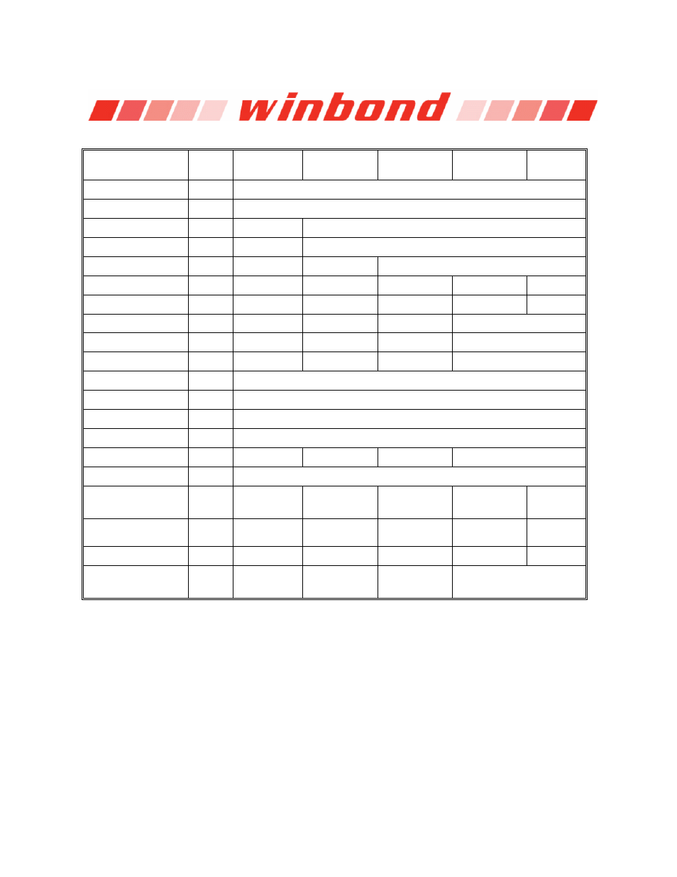
10.2.2 Instruction Set Table 1
(1)
INSTRUCTION
NAME
BYTE 1
(CODE)
BYTE 2
BYTE 3
BYTE 4
BYTE 5
BYTE 6
Write Enable
06h
Write Disable
04h
Read Status Register-1
05h
(S7–S0)
2
Read Status Register-2
35h
(S15-S8)
2
Write Status Register
01h
(S7–S0) (S15-S8)
Page Program
02h
A23–A16 A15–A8 A7–A0 (D7–D0)
Quad Page Program
32h
A23–A16 A15–A8 A7–A0 (D7–D0,
…)
3
Block Erase (64KB)
D8h
A23–A16 A15–A8 A7–A0
Block Erase (32KB)
52h
A23–A16 A15–A8 A7–A0
Sector Erase (4KB)
20h
A23–A16 A15–A8 A7–A0
Chip Erase
C7h/60h
Erase Suspend
75h
Erase Resume
7Ah
Power-down
B9h
High Performance Mode
A3h
dummy dummy dummy
Mode Bit Reset
(4)
FFh
Release Power down or
HPM / Device ID
ABh
dummy dummy dummy
(ID7-ID0)
5
Manufacturer/
Device ID
(6)
90h
dummy dummy
00h (M7-M0)
(ID7-ID0)
Read Unique ID
4Bh
dummy dummy dummy Dummy
(ID63-ID0)
JEDEC ID
9Fh
(M7-M0)
Manufacturer
(ID15-ID8)
Memory Type
(ID7-ID0)
Capacity
Notes:
1. Data bytes are shifted with Most Significant Bit first. Byte fields with data in parenthesis “()” indicate data being
read from the device on the DO pin.
2. The Status Register contents will repeat continuously until /CS terminates the instruction.
3. Quad Page Program Input Data
IO0 = (D4, D0, ……)
IO1 = (D5, D1, ……)
IO2 = (D6, D2, ……)
IO3 = (D7, D3, ……)
4. This instruction is recommended when using the Dual or Quad Mode bit feature. See section 10.2.28 for more
information.
5. The Device ID will repeat continuously until /CS terminates the instruction.
6. See Manufacturer and Device Identification table for Device ID information.