2 instructions, 1 manufacturer and device identification, Instructions – Rainbow Electronics W25Q32 User Manual
Page 18: Manufacturer and device identification
W25Q80, W25Q16, W25Q32
- 18 -
10.2 INSTRUCTIONS
The instruction set of the W25Q80/16/32 consists of fifteen basic instructions that are fully controlled
through the SPI bus (see Instruction Set table). Instructions are initiated with the falling edge of Chip
Select (/CS). The first byte of data clocked into the DI input provides the instruction code. Data on the
DI input is sampled on the rising edge of clock with most significant bit (MSB) first.
Instructions vary in length from a single byte to several bytes and may be followed by address bytes,
data bytes, dummy bytes (don’t care), and in some cases, a combination. Instructions are completed
with the rising edge of edge /CS. Clock relative timing diagrams for each instruction are included in
figures 4 through 19. All read instructions can be completed after any clocked bit. However, all
instructions that Write, Program or Erase must complete on a byte boundary (CS driven high after a full
8-bits have been clocked) otherwise the instruction will be terminated. This feature further protects the
device from inadvertent writes. Additionally, while the memory is being programmed or erased, or when
the Status Register is being written, all instructions except for Read Status Register will be ignored until
the program or erase cycle has completed.
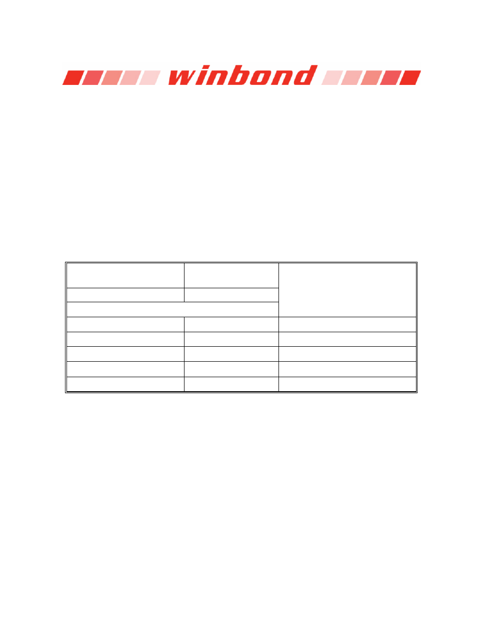
10.2.1 Manufacturer and Device Identification
MANUFACTURER ID
(M7-M0)
Winbond Serial Flash
EFh
Device ID
(ID7-ID0)
(ID15-ID0)
Instruction
ABh,
90h
9Fh
W25Q80 13h
4014h
W25Q16 14h
4015h
W25Q32 15h
4016h