C control channel – Rainbow Electronics MAX9258 User Manual
Page 45
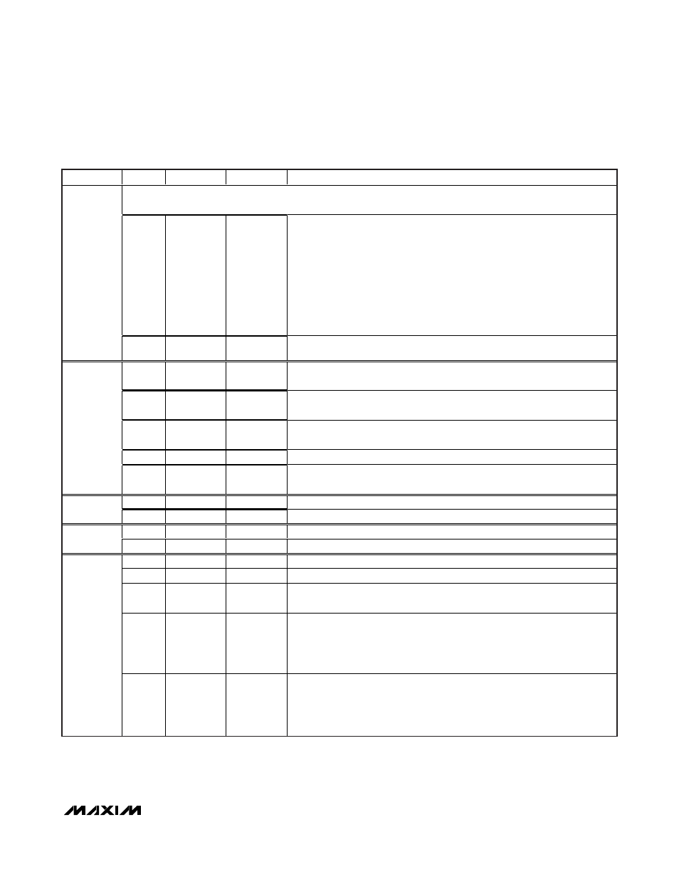
MAX9257/MAX9258
______________________________________________________________________________________
45
Fully Programmable Serializer/Deserializer
with UART/I
2
C Control Channel
ADDRESS
BITS
DEFAULT
NAME
DESCRIPTION
Control channel end timeout: (ETO) times out if ECU does not use control channel for this amount of time after it has
already used at least once.
7:4
1010
ETODIV
Control channel end timeout divider
Pixel clock is first divided by:
0000 = 16
1000 = 256
0001 = 16
1001 = 512
0010 = 16
1010 = 1024 (default)
0011 = 16
1011 = 2048
0100 = 16
1100 = 4096
0101 = 32
1101 = 8192
0110 = 64
1110 = 16,384
0111 = 128
1111 = 32,768
3
3:0
0000
ETOCNT
Control channel end timeout counter
Divided pixel clock is used to count up to (ETOCNT + 1)
7
0
VEDGE
VSYNC active edge at ECU interface
0 = falling (default), 1 = rising
6
0
HEDGE
HSYNC active edge at ECU interface
0 = falling (default), 1 = rising
5
1
CKEDGE
PCLK active edge at ECU interface
0 = falling, 1 = rising (default)
4:1
0000
Reserved (set to 0000)
4
0
0
PRBSEN
PRBS test enable
0 = disabled (default), 1 = enabled
7:1
1111100
DEVICEID
7-bit address of MAX9258
5
0
0
Reserved (set to 0)
7:1
1111111
EF
End frame to close control channel
6
0
1
Reserved (set to 1)
7
0
INTMODE
Interface mode
0 = UART (default), 1 = I
2
C
6
0
INTEN
Interface enable
0 = disabled (default), 1 = enabled
5
0
FAST
Fast UART transceiver
0 = bit rate = DC to 4.25Mbps (default), 1 = bit rate = 4.25Mbps to 10 Mbps
4:2
000
CTO
Timer to come back from bypass mode (in bit time)
000 = never come back (default)
100 = 64
001 = 16
101 = 80
010 = 32
110 = 96
011 = 48
111 = 112
7
1:0
00
BITRATE
Control channel bit rate range in base mode
00 = 95kbps to 400kbps (default)
01 = 400kbps to 1000kbps
10 = 1000kbps to 4250kbps
11 = 1000kbps to 4250kbps
MAX9258 Register Table (continued)