C control channel, Max9257 register table – Rainbow Electronics MAX9258 User Manual
Page 20
MAX9257/MAX9258
20
______________________________________________________________________________________
Fully Programmable Serializer/Deserializer
with UART/I
2
C Control Channel
REGISTER NAME
REGISTER
ADDRESS (hex)
POWER-UP VALUE
(hex)
POWER-UP DEFAULT SETTINGS
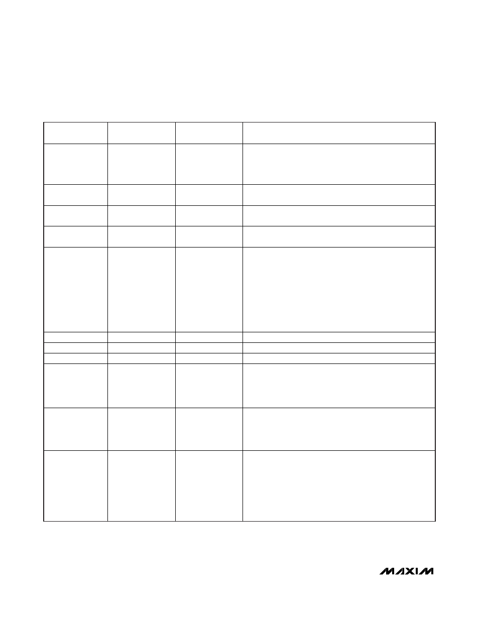
REG0
0x00
0xB5
PRATE = 10, 20MHz to 40MHz
SRATE = 11, 400Mbps to 840Mbps
PAREN = 0, parity disabled
PWIDTH = 101, parallel data width = 18
REG1
0x01
0x1F
SPREAD = 000, spread = off
Reserved = 11111
REG2
0x02
0xA0
STODIV = 1010, STO clock is pixel clock divided by 1024
STOCNT = 0000, STO counter counts to 1
REG3
0x03
0xA0
ETODIV = 1010, ETO clock is pixel clock divided by 1024
ETOCNT = 0000, ETO counter counts to 1
REG4
0x04
1) REM = 0, 0x28
2) REM = 1, 0x30
VEDGE = 0, VSYNC active edge is falling
Reserved = 0
CKEDGE = 1, pixel clock active edge is rising
PD: 1) If REM = 0, PD = 0
2) If REM = 1, PD = 1
SEREN: 1) If REM = 0, SEREN = 1
2) If REM = 1, SEREN = 0
BYPFPLL = 0, filter PLL is active
Reserved = 0
PRBSEN = 0, PRBS test disabled
REG5
0x05
0xFA
MAX9257 address = 1111 1010
REG6
0x06
0xFF
End frame = 1111 1111
REG7
0x07
0xF8
MAX9258 address = 1111 1000
REG8
0x08
0x00
INTMODE = 0, interface with peripheral is UART
INTEN = 0, interface with peripheral is disabled
FAST = 0, UART bit rate = DC to 4.25Mbps
CTO = 000, never come back
BITRATE = 00, base mode bit rate = 95kbps to 400kbps
REG9
0x09
0x00
PRBSLEN = 0000, PRBS word length = 2
21
GPIO9DIR = 0, GPIO9 = input
GPIO8DIR = 0, GPIO8 = input
GPIO9 = 0
GPIO8 = 0
REG10
0x0A
0x00
GPIO7DIR = 0, GPIO7 = input
GPIO6DIR = 0, GPIO6 = input
GPIO5DIR = 0, GPIO5 = input
GPIO4DIR = 0, GPIO4 = input
GPIO3DIR = 0, GPIO3 = input
GPIO2DIR = 0, GPIO2 = input
GPIO1DIR = 0, GPIO1 = input
GPIO0DIR = 0, GPIO0 = input
Table 1. MAX9257 Power-Up Default Register Map (see the
MAX9257 Register Table
)