C control channel – Rainbow Electronics MAX9258 User Manual
Page 24
MAX9257/MAX9258
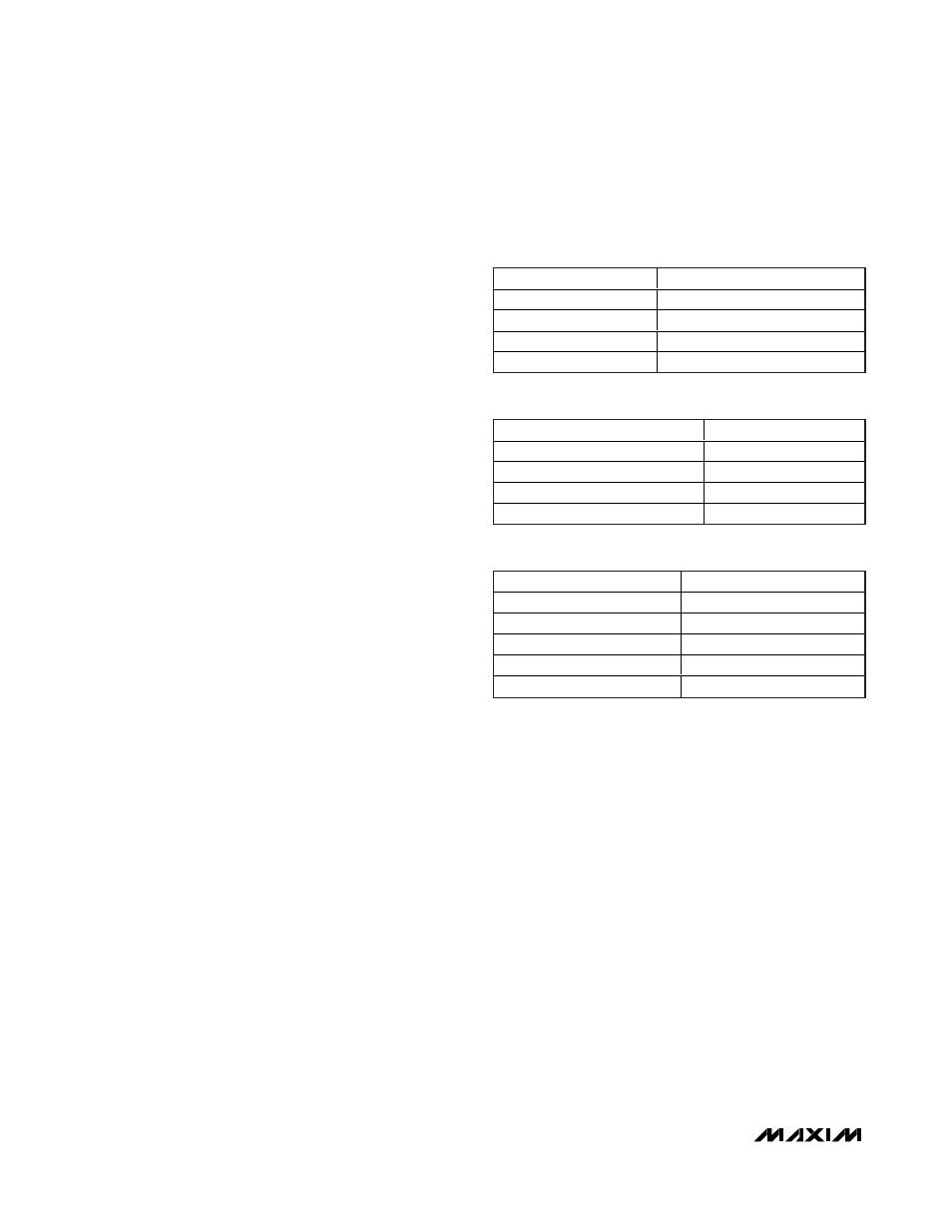
Pixel Clock Frequency Range
The MAX9257/MAX9258 each have registers that can
be configured at startup. Depending on the word
length, the MAX9257 multiplies PCLK_IN (pixel clock)
by 12, 14, 16, 18, or 20 using an internal PLL to gener-
ate the serial clock. Use Table 20 for proper selection
of available PCLK frequency and serial-data ranges.
Parallel data is serialized using the serial-clock and
serialized bits are transmitted at the MAX9257 LVDS
outputs. The MAX9257/MAX9258 support a wide range
for PCLK_IN (Table 14). If the pixel clock frequency
needs to change to a frequency outside the pro-
grammed range, the ECU must program both the
MAX9257 and the MAX9258 in the same control chan-
nel session.
Serial-Data Rate Range
The word length and pixel clock is limited by the maxi-
mum serial-data rate of 840Mbps. The following formula
shows the relation between word length, pixel clock,
and serial clock:
Serial-word length x pixel clock = serial-data rate
≤
840Mbps
For example, if PCLK_IN is 70MHz, the serial-word
length has to be 12 bits including DC balance bits if
parity is not enabled to keep the serial-data rate under
840Mbps. If the serial-word length is 20 bits, the maxi-
mum PCLK_IN frequency is 42MHz. The serial-data
rate can vary from 60Mbps to 840Mbps and can be
programmed at power-up (Table 15). Use Table 20 for
proper selection of available PCLK frequency and serial
data ranges. Operating in the incorrect range for either
the serial-data rate or PCLK_IN can result in excessive
current dissipation and failure of the MAX9258 to lock
to the MAX9257.
LVDS Common-Mode Bias
The output common-mode bias is 1.2V at the LVDS
inputs on the MAX9258 and LVDS outputs on the
MAX9257. No external resistors are required to provide
bias for AC-coupling the LVDS inputs and outputs.
LVDS Termination
Terminate the LVDS link at both ends with the charac-
teristic impedance of the transmission line (typically
100Ω differential). The LVDS inputs and outputs are
high impedance to GND and differentially.
Spread-Spectrum Selection
The MAX9257/MAX9258 each have spread-spectrum
options. Both should not be turned on at the same time.
When the MAX9257 is programmed for spread spectrum,
the MAX9258 tracks and passes the spread to its clock
and data outputs. The MAX9257/MAX9258 are both
center spread (Figure 21). The control channel does
not use spread spectrum, but has slower transition
times.
MAX9258 Spread Spectrum
The MAX9258 features a programmable spread-spec-
trum clock and data outputs for reduced EMI. The sin-
gle-ended data outputs are programmable for no
spread, ±2%, or ±4% (see the
Typical Operating
Characteristics
) around the recovered pixel clock fre-
quency. The output spread is programmed in register
REG1[7:6]. Table 17 shows the spread options, and
Table 18 shows the various modulation rates.
MAX9257 Spread Spectrum
The MAX9257 features programmable spread spectrum
for the LVDS outputs. Table 19 shows various spread
options, and Table 20 shows the various modulation
rates. Only one device (the MAX9257 or the MAX9258)
should be programmed for spread spectrum at a time. If
the MAX9257 is programmed for spread, the MAX9258
24
______________________________________________________________________________________
Fully Programmable Serializer/Deserializer
with UART/I
2
C Control Channel
FREQUENCY (MHz)
PRATE (REG0[7:6])
5–10
00
10–20
01
20–40
10
40–70
11
Table 14. MAX9257 Pixel Clock Range
(PCLK_IN)
SERIAL-DATA RATE (Mbps)
SRATE (REG0[5:4])
60–100
00
100–200
01
200–400
10
400–840
11
Table 15. Serial-Data Rate Range
PARALLEL-WORD WIDTH
PWIDTH (REG0[2:0])
10
000
12
001
14
010
16
011
18
1XX
Table 16. Parallel-Word Width