C control channel, Detailed description – Rainbow Electronics MAX9258 User Manual
Page 18
MAX9257/MAX9258
Detailed Description
The MAX9257 serializer pairs with the MAX9258 deseri-
alizer to form a complete digital video serial link. The
electronic control unit (ECU) programs the registers in
the MAX9257, MAX9258, and peripheral devices, such
as a camera, during the control channel phase that
occurs at startup or during the vertical blanking time.
All control channel communication is half-duplex. The
UART communication between the MAX9258 and the
MAX9257 is encoded to allow transmission through AC-
coupling capacitors. The MAX9257 communicates to
the peripheral device through UART or I
2
C.
The MAX9257/MAX9258 DC-balanced serializer and
deserializer operate from a 5MHz-to-70MHz parallel
clock frequency, and are capable of serializing and
deserializing programmable 10, 12, 14, 16, and 18 bits
parallel data during the video phase. The MAX9257/
MAX9258 have two phases of operation: video and
control channel (Figures 19 and 20). During the video
phase, the MAX9257 accepts parallel video data and
transmits serial encoded data over the LVDS link. The
MAX9258 accepts the encoded serial LVDS data and
converts it back to parallel output data. The MAX9257
has dedicated inputs for HSYNC and VSYNC. The
selected VSYNC edge causes the MAX9257/MAX9258
to enter the control channel phase. Nonactive VSYNC
edge can be asserted after eight pixel clock cycles.
The video data are coded using two overhead bits
(EN0 and EN1) resulting in a serial-word length of N+2
bits. The MAX9257/MAX9258 feature programmable
18
______________________________________________________________________________________
Fully Programmable Serializer/Deserializer
with UART/I
2
C Control Channel
MAX9258
I
2
C
UART-
TO-I
2
C
UART
UART
CAMERA
ECU
DESERIALIZER
MAX9257
SERIALIZER
VIDEO DATA
PIXEL CLOCK
LOCK
HSYNC_OUT
VSYNC_OUT
RX
TX
ERROR
PD
CCEN
VIDEO DATA
PIXEL CLOCK
HSYNC_IN
VSYNC_IN
SDA
SCL
GPIO
100
Ω
100
Ω
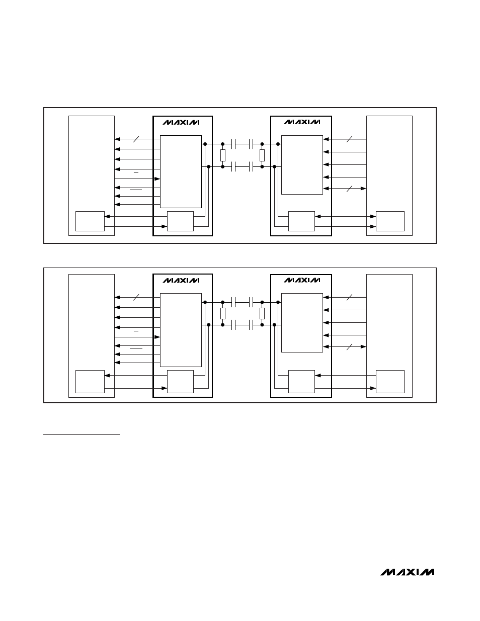
Figure 17. Serial Link with I
2
C Camera Programming Interface (Base Mode)
MAX9258
UART
UART
UART
UART
CAMERA
ECU
DESERIALIZER
MAX9257
SERIALIZER
VIDEO DATA
PIXEL CLOCK
HSYNC_OUT
VSYNC_OUT
RX
TX
ERROR
PD
CCEN
LOCK
VIDEO DATA
PIXEL CLOCK
HSYNC_IN
VSYNC_IN
RX
TX
GPIO
100
Ω
100
Ω
Figure 18. Serial Link with UART Camera Programming Interface (Bypass Mode)