C control channel – Rainbow Electronics MAX9258 User Manual
Page 42
MAX9257/MAX9258
42
______________________________________________________________________________________
Fully Programmable Serializer/Deserializer
with UART/I
2
C Control Channel
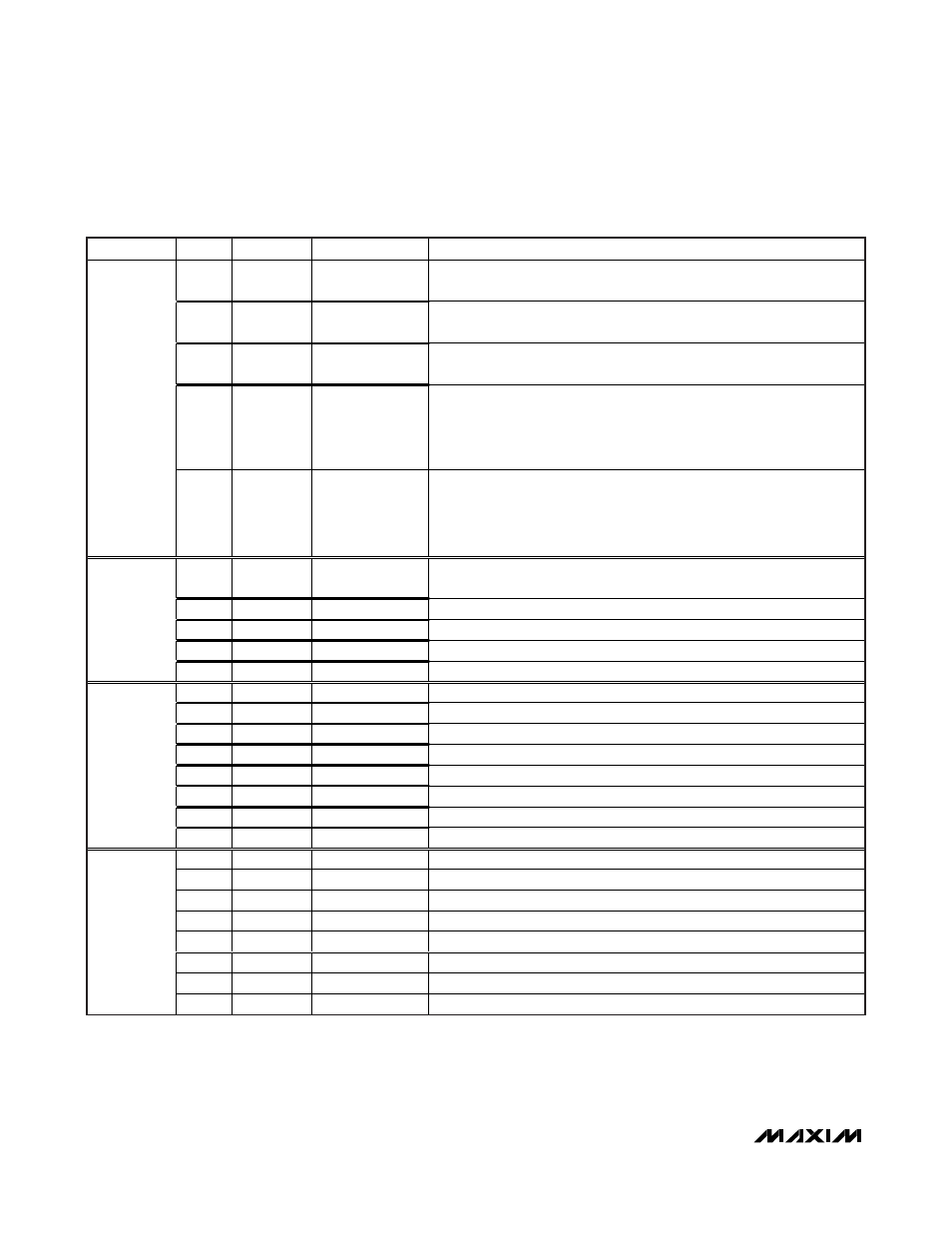
ADDRESS
BITS
DEFAULT
NAME
DESCRIPTION
7
0
INTMODE
Interface mode
0 = UART (default), 1 = I
2
C
6
0
INTEN
Interface enable
0 = disabled (default), 1 = enabled
5
0
FAST
Fast UART transceiver
0 = b i t r ate = D C to 4.25M b p s ( d efaul t) , 1 = b i t r ate = 4.25M b p s to 10M b p s
4:2
000
CTO
Timer to come back from bypass mode (in bit time)
000 = never come back (default)
100 = 64
001 = 16
101 = 80
010 = 32
110 = 96
011 = 48
111 = 112
8
1:0
00
BITRATE
Control channel bit rate range in base mode
00 = 95kbps to 400kbps (default)
01 = 400kbps to 1000kbps
10 = 1000kbps to 4250kbps
11 = 1000kbps to 4250kbps
7:4
0000
PRBSLEN
PRBS test number of words
1111 = continuous
else = 2
(PRBSLEN + 21)
3
0
GPIO9DIR
GPIO 9 direction
0 = input (default), 1 = output
2
0
GPIO8DIR
GPIO 8 direction
0 = input (default), 1 = output
1
0
GPIO9*
General purpose input output 9
9
0
0
GPIO8*
General purpose input output 8
7
0
GPIO7DIR
GPIO 7 direction
0 = input (default), 1 = output
6
0
GPIO6DIR
GPIO 6 direction
0 = input (default), 1 = output
5
0
GPIO5DIR
GPIO 5 direction
0 = input (default), 1 = output
4
0
GPIO4DIR
GPIO 4 direction
0 = input (default), 1 = output
3
0
GPIO3DIR
GPIO 3 direction
0 = input (default), 1 = output
2
0
GPIO2DIR
GPIO 2 direction
0 = input (default), 1 = output
1
0
GPIO1DIR
GPIO 1 direction
0 = input (default), 1 = output
10
0
0
GPIO0DIR
GPIO 0 direction
0 = input (default), 1 = output
7
0
GPIO7*
General purpose input output 7
6
0
GPIO6*
General purpose input output 6
5
0
GPIO5*
General purpose input output 5
4
0
GPIO4*
General purpose input output 4
3
0
GPIO3*
General purpose input output 3
2
0
GPIO2*
General purpose input output 2
1
0
GPIO1*
General purpose input output 1
11
0
0
GPIO0*
General purpose input output 0
MAX9257 Register Table (continued)