C control channel – Rainbow Electronics MAX9258 User Manual
Page 44
MAX9257/MAX9258
44
______________________________________________________________________________________
Fully Programmable Serializer/Deserializer
with UART/I
2
C Control Channel
ADDRESS
BITS
DEFAULT
NAME
DESCRIPTION
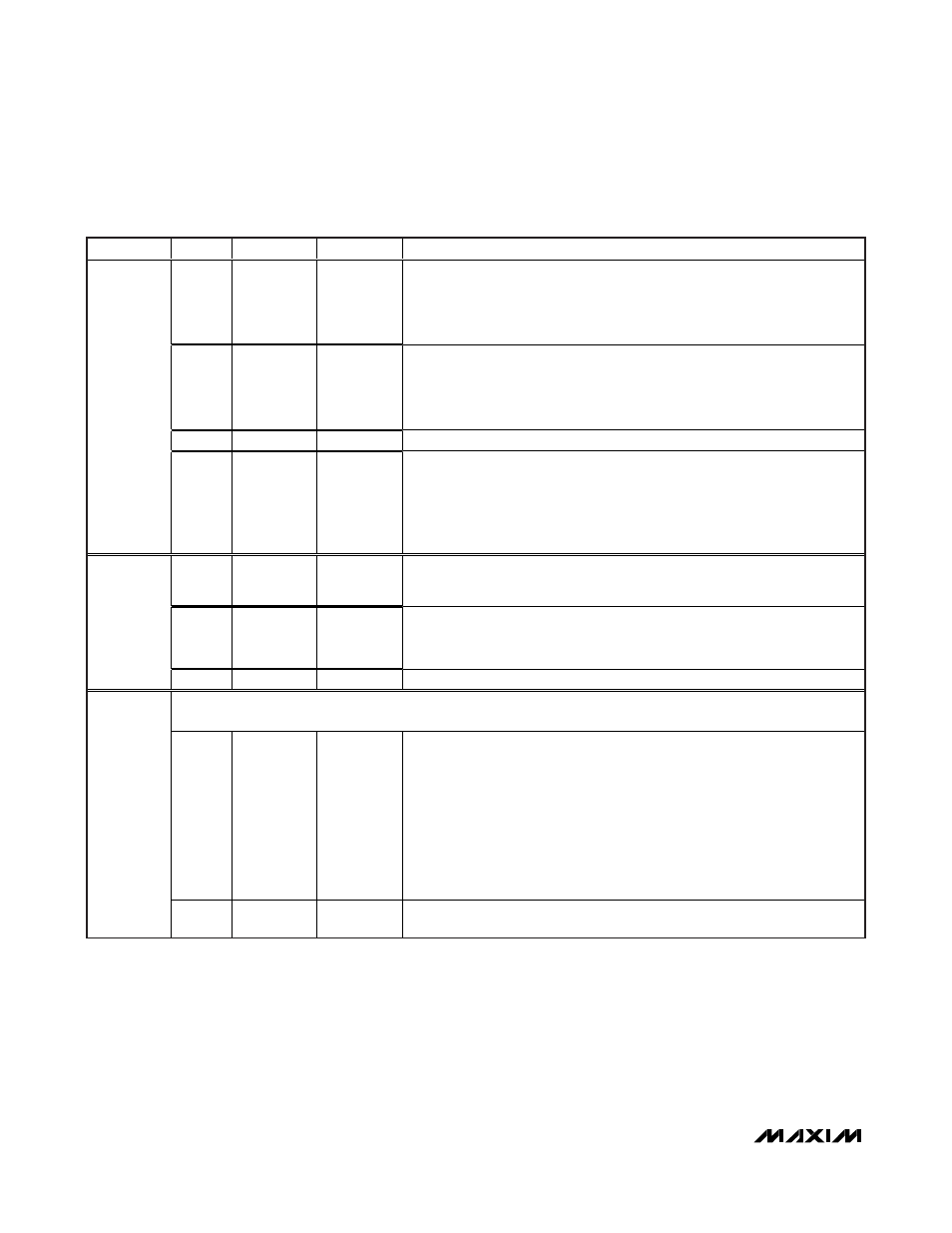
7:6
10
PRATE
Pixel clock frequency range
00 = 5MHz to 10MHz
01 = 10MHz to 20MHz
10 = 20MHz to 40MHz (default)
11 = 40MHz to 70MHz
5:4
11
SRATE
Serial-data rate range
00 = 60Mbps to 100Mbps
01 = 100Mbps to 200Mbps
10 = 200Mbps to 400Mbps
11 = 400Mbps to 840Mbps (default)
3
0
PAREN
Parity enable
0 = disabled (default), 1 = enabled
0
2:0
101
PWIDTH
Parallel data width
(includes HSYNC and VSYNC, excludes encoding and parity bits)
000 = 10
100 = 18
001 = 12
101 = 18 (default)
010 = 14
110 = 18
011 = 16
111 = 18
7:6
00
SPREAD
Spread-spectrum setting
00 = Off (default)
10 = Off
01 = 2%
11 = 4%
5
0
AER
Autoerror reset
1 = Reset error count when control channel ends.
0 = Reset upon reading error registers 10, 11, 13 (default)
1
4:0
00000
Reserved (set to 000000)
Control channel start timeout: (STO) times out if ECU does not start using control channel within this amount of time
after control channel session is enabled.
7:4
1010
STODIV
Control channel start timeout divider
Pixel clock is first divided by :
0000 = 16
1000 = 256
0001 = 16
1001 = 512
0010 = 16
1010 = 1024 (default)
0011 = 16
1011 = 2048
0100 = 16
1100 = 4096
0101 = 32
1101 = 8192
0110 = 64
1110 = 16,384
0111 = 128
1111 = 32,768
2
3:0
0000
STOCNT
Control channel start timeout counter
Divided pixel clock is used to count up to (STOCNT + 1)
MAX9258 Register Table