C control channel, Video data parity, Ac-coupling benefits – Rainbow Electronics MAX9258 User Manual
Page 38: Selection of ac-coupling capacitors
MAX9257/MAX9258
38
______________________________________________________________________________________
Fully Programmable Serializer/Deserializer
with UART/I
2
C Control Channel
performed with or without spread spectrum. If the PRBS
test is programmed to run continuously, the MAX9257
must be powered down to stop the test. When pro-
grammed for a finite number of repetitions, the control
channel is enabled after the PRBS test finishes and
serialization enable (SEREN) is reset to 0. To start nor-
mal operation, the ECU must disable PRBSEN and
enable SEREN.
Video Data Parity
Parity protection of video data is programmable for par-
allel-word widths of 16 bits or less. When programmed,
two parity bits are appended to each parallel word
latched into the MAX9257. In the MAX9258, a 16-bit
parity error counter logs parity errors. The
ERROR out-
put on the MAX9258 goes low if parity errors exceed a
programmable threshold.
AC-Coupling Benefits
AC-coupling increases the input voltage of the LVDS
receiver to the voltage rating of the capacitor. Two
capacitors are sufficient for isolation, but four capaci-
tors—two at the serializer output and two at the deseri-
alizer input—provide protection if either end of the
cable is shorted to a high voltage. AC-coupling blocks
low-frequency ground shifts and common-mode noise.
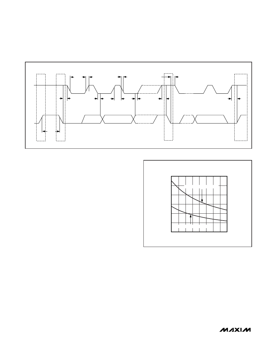
Selection of AC-Coupling Capacitors
See Figure 31 for calculating the capacitor values for
AC-coupling depending on the parallel clock frequency.
The plot shows minimum capacitor values for two- and
four-capacitor-per-link systems. To block the highest
common-mode frequency shift, choose the minimum
capacitor value shown in Figure 31. In general, 0.1µF
capacitors are sufficient.
Optimally Choosing AC-Coupling Capacitors
Voltage droop and the digital sum variaton (DSV) of trans-
mitted symbols cause signal transitions to start from dif-
ferent voltage levels. Because the transition time is finite,
starting the signal transition from different voltage levels
causes timing jitter. The time constant for an AC-coupled
link needs to be chosen to reduce droop and jitter to an
acceptable level. The RC network for an AC-coupled link
consists of the LVDS receiver termination resistor (R
TR
),
AC-COUPLING CAPACITOR VALUE
vs. SERIAL-DATA RATE
SERIAL-DATA RATE (Mbps)
CAPACITOR VALUE (nF)
780
720
660
600
540
480
420
20
40
60
0
360
840
FOUR CAPACITORS PER LINK
TWO CAPACITORS PER LINK
Figure 31. AC-Coupling Capacitor Values vs. Clock Frequency
from 18MHz to 42MHz
P
t
BUF
t
R
t
HD;STA
P
S
S
t
HD;STA
t
LOW
t
HD;DAT
t
HIGH
t
F
t
SU;DAT
t
SU;STA
t
SU;STO
SCL
SDA
Figure 30. I
2
C Timing Parameters