C control channel, Applications information, Table 31. timing information for i – Rainbow Electronics MAX9258 User Manual
Page 37: C data rates greater than 400kbps
MAX9257/MAX9258
______________________________________________________________________________________
37
Fully Programmable Serializer/Deserializer
with UART/I
2
C Control Channel
PARAMETER
SYMBOL
MIN
TYP
MAX
UNIT
SCL Clock Frequency
f
SCL
1
1
t
UCLK*
Start Condition Hold Time
t
HD:STA
1
1
t
UCLK
Low Period of SCL Clock
t
LOW
0.5
0.5
t
UCLK
High Period of SCL Clock
t
HIGH
0.5
0.5
t
UCLK
Repeated START Condition
Setup Time
t
SU:STA
0.25
0.25
t
UCLK
Data Hold Time
t
HD:DAT
0.25
0.25
t
UCLK
Data Setup Time
t
SU:DAT
0.25
0.25
t
UCLK
Setup Time for STOP Condition
t
SU:STO
0.25
0.25
t
UCLK
Bus Free Time
t
BUF
0.5
0.5
t
UCLK
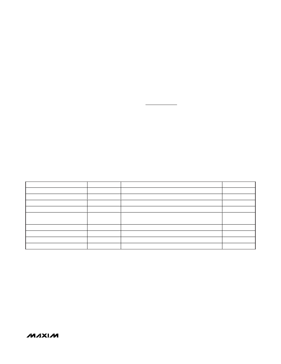
Table 31. Timing Information for I
2
C Data Rates Greater than 400kbps
*
t
UCLK
is equal to one UART period.
I
2
C
The MAX9257 features a UART-to-I
2
C converter that
converts UART packets to I
2
C. The UART-to-I
2
C con-
verter works as a repeater between the ECU and exter-
nal I
2
C slave devices. The MAX9257 acts as the master
and converts UART read/write packets from the ECU to
I
2
C read/write for external I
2
C slave devices. For writes,
the UART-to-I
2
C converts the UART packets received
directly into I
2
C. For reads, the UART-to-I
2
C converter
follows the UART packet protocol. The I
2
C SCL clock
period is approximately the same as the UART bit clock
period (t
UCLK
). The I
2
C speed varies with UART speed.
I
2
C reads from the peripheral device do not disable the
ETO timer. Choose ETO large enough so that I
2
C read
commands are not lost due to ETO timing out.
I
2
C Timing
The MAX9257 acts like a master in I
2
C communication
with the peripheral device. The MAX9257 takes less
than 22 UART bit times to convert UART packets into
I
2
C. The SCL and SDA timings are based on the UART
bit clock. The I
2
C data rate is determined by UART and
can range from 95kbps to 4.25Mbps. The I
2
C timing
requirements scale linearly from fast mode to higher
speeds. Table 31 shows the I
2
C timing information for
data rates greater than 400kbps. The I
2
C parameters
scale with t
UCLK
. See Figure 30 for timing parameters.
Applications Information
PRBS Test
The MAX9257/MAX9258 have built-in circuits for testing
bit errors on the serial link. The MAX9257 has a PRBS
generator and the MAX9258 has a PRBS checker. The
length of the PRBS pattern is programmable from 2
21
to
2
35
word length or continuous by programming
REG9[7:4] in the MAX9257. In case of errors, errors are
counted in the MAX9258 PRBSERR register (REG12),
and the
ERROR output on the MAX9258 goes low. To
start the test, the ECU writes a 1 to PRBSEN bit of both
the MAX9257 and the MAX9258. The PRBS test can be