C control channel – Rainbow Electronics MAX9258 User Manual
Page 40
MAX9257/MAX9258
40
______________________________________________________________________________________
Fully Programmable Serializer/Deserializer
with UART/I
2
C Control Channel
ADDRESS
BITS
DEFAULT
NAME
DESCRIPTION
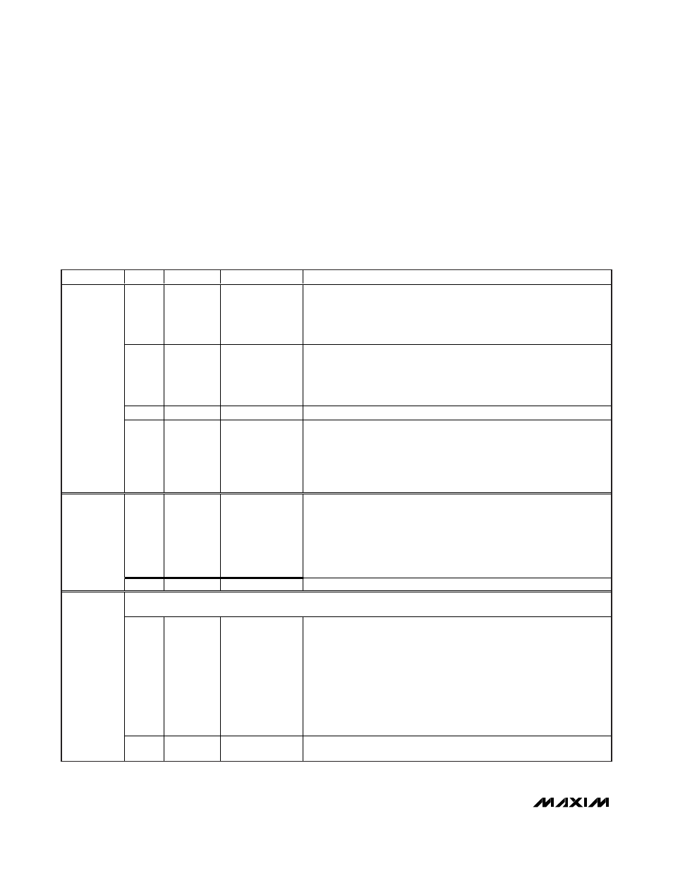
7:6
10
PRATE
Pixel clock frequency range
00 = 5MHz to 10MHz
01 = 10MHz to 20MHz
10 = 20MHz to 40MHz (default)
11 = 40MHz to 70MHz
5:4
11
SRATE
Serial-data rate range
00 = 60Mbps to 100Mbps
01 = 100Mbps to 200Mbps
10 = 200Mbps to 400Mbps
11 = 400Mbps to 840Mbps (default)
3
0
PAREN
Parity enable
0 = disabled (default), 1 = enabled
0
2:0
101
PWIDTH
Parallel data width
(includes HSYNC and VSYNC, excludes DCB, INV, and parity bits)
000 = 10
100 = 18
001 = 12
101 = 18 (default)
010 = 14
110 = 18
011 = 16
111 = 18
7:5
000
SPREAD
Spread-spectrum setting
For PRATE ranges 00, 01: all spread options possible
For PRATE ranges 10, 11: maximum spread is 2%
000 = Off (default)
100 = Off
001 = 1.5%
101 = 3%
010 = 1.75%
110 = 3.5%
011 = 2%
111 = 4%
1
4:0
11111
Reserved (set to 11111)
Control channel start timeout: (STO) times out if ECU does not start using control channel within this amount of time
after control channel session is enabled.
7:4
1010
STODIV
Control channel start timeout divider
Pixel clock is first divided by:
0000 = 16
1000 = 256
0001 = 16
1001 = 512
0010 = 16
1010 = 1024 (default)
0011 = 16
1011 = 2048
0100 = 16
1100 = 4096
0101 = 32
1101 = 8192
0110 = 64
1110 = 16,384
0111 = 128
1111 = 32,768
2
3:0
0000
STOCNT
Control channel start timeout counter
Divided pixel clock is used to count up to (STOCNT + 1)
MAX9257 Register Table
Choosing I
2
C Pullup Resistors
I
2
C requires pullup resistors to provide a logic-high level
to data and clock lines. There are tradeoffs between
power dissipation and speed, and a compromise must
be made in choosing pullup resistor values. Every device
connected to the bus introduces some capacitance even
when device is not in operation. I
2
C specifies 300ns rise
times to go from low to high (30% to 70%) for fast mode,
which is defined for a date rate up to 400kbps (see I
2
C
specifications for details). To meet the rise time require-
ment, choose the pullup resistors so the rise time
t
R
= 0.85R
PULLUP
x C
BUS
< 300ns. If the transition time
becomes too slow, the setup and hold times may not be
met and waveforms will not be recognized.