C control channel, Table 28. control channel data rate in base mode, Table 29. control channel data rate in bypass mode – Rainbow Electronics MAX9258 User Manual
Page 36: Table 30. default device address
MAX9257/MAX9258
36
______________________________________________________________________________________
Fully Programmable Serializer/Deserializer
with UART/I
2
C Control Channel
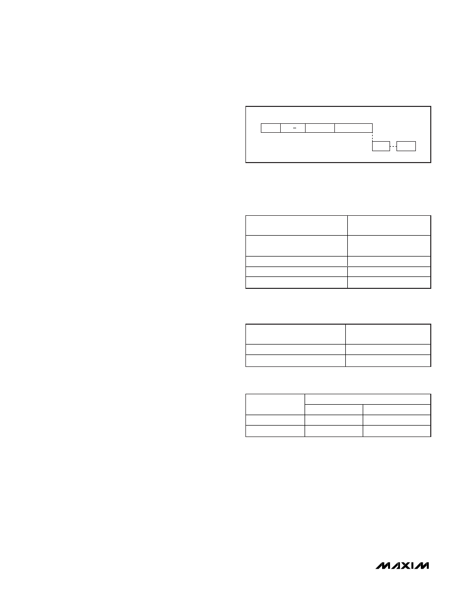
Read Packet
The ECU writes the sync frame, 7-bit device address
plus read/write bit (R/
W = 1 for read), 8-bit register
address, and number of bytes to be read. The
addressed device responds with read data bytes
(Figure 29). UART read delay is maximum 4 bit times
when reading from the MAX9257 or the MAX9258.
Time Between Frames
Up to two high bit times are allowed between frames.
Reset of Packet Boundary
A high time ranging from 14 UART bit times or more
resets the packet boundary. In this case, the next frame
received is assumed to belong to a new packet by the
MAX9257/MAX9258 and UART-to-I
2
C converter.
Resetting the boundary is required. Not resetting the
boundary treats the following packets as part of the first
packet, and they may be processed incorrectly.
Data Rate
The control channel data rate in base mode is between
95kbps to 4.25Mbps (Table 28). In bypass mode, the
allowed data rate is DC to 10Mbps (Table 29). For data
rates faster than 4.25Mbps in bypass mode, REG8[5] in
MAX9257 and REG7[5] in MAX9258 must be set high.
Set the control channel data rate in base mode by writ-
ing to REG8[1:0] in the MAX9257 and REG7[1:0] in the
MAX9258. These write commands take effect in the
next control channel.
Programming the FAST bit takes effect in the same con-
trol channel. Both the MAX9257 and the MAX9258
should have the same settings for FAST. It is recom-
mended to first program the FAST bit in the MAX9257.
Programming FAST to 1 results in shorter UART pulses
on the differential link.
MAX9257/MAX9258 Device
Address Programming
The MAX9257/MAX9258 have device addresses that
can be programmed to any 7-bit address. Table 30
shows the default addresses.
MAX9257 REG8[1:0]
MAX9258 REG7[1:0]
RANGE
00
95kbps–400kbps
(default)
01
400kbps–1Mbps
10
1Mbps–4.25Mbps
11
1Mbps–4.25Mbps
Table 28. Control Channel Data Rate in
Base Mode
MAX9257 REG8[5]
MAX9258 REG7[5]
RANGE
0
DC–4.25Mbps
1
4.25Mbps–10Mbps
Table 29. Control Channel Data Rate in
Bypass Mode
DEFAULT
DEVICE
BINARY
HEX
MAX9257
1111 1010
0xFA
MAX9258
1111 1000
0xF8
Table 30. Default Device Address
NUMBER OF BYTES
REG ADDRESS
BYTE 1
BYTE N
DEV ADDR +
R/W
SYNC
Figure 29. UART Read Packet