Gpi cabling, Gpi cable connections – Cobalt Digital COMPASS 9229-QS Quad-Split Video Processor User Manual
Page 24
2-10
••••
Installation
9229-QS User Manual
••••
(V 1.2)
GPI Cabling
The 9229-QS includes eight General Purpose Input (GPI) pins to interface with external equipment.
There are eight input pins labeled GPIO 1-8 on the terminal block of the Rear Module (Figure 2.4 ,
Figure 2.5 , or Figure 2.6 ). Ports are pre-configured to be only an input (GPI). Electrically, the ports
are setup for contact closure to ground, with a 1Kohm pull-up resistor to +5V, and default to a logical
high state.
Note
— The default state for the GPI/O contacts is active low signaling. If a GPI cable
is absent from the Rear Module, no GPI will be triggered and executed inadvertently by
the card.
GPI Cable Connections
The GPI ports are available on four 3-pin WECO® connectors located on the Rear Module. Four 3-pin
mating WECO® plugs are provided with the Rear Module. This section provides information for
connecting GPI/Tally cables to the installed Rear Modules of the 20-slot frame.
Use the following procedure to cable the rear module for GPIs:
1.
Locate the GPI ports on the Rear Module. Refer to the Rear Module labeling and Refer
to the section “Cabling” for port locations.
2.
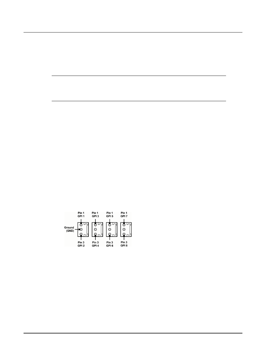
Wire the GPI ports as follows:
The left and right pins are the two GPI signals while the center pin is the common
Ground (GND).
Refer to Figure 2.9 for GPI configuration on the Rear Module.
F
Figure 2.9
RM20-9229-C GPI Connections
This completes the procedure for cabling the rear module for GPIs. For details on setting up the
communications for the GPI ports, refer to the section “GPI Communication Setup”.