4 take 4 … 20 ma test signal, 5 load, 6 connection control – VEGA VEGADIF 55 4 … 20 mA_HART User Manual
Page 30: Test, 4 take 4 … 20 ma test signal
5
.4 Take 4 … 20 mA test signal
W
ithout interrupting the measurement you can tap a 4 … 20 mA test
signal via the plug and test terminal. By simply switching the bridges,
you can lower the min. supply voltage of the measuring instrument.
T
hrough this it also possible to operate the instrument with a weaker
voltage source. To keep the measurement error below 0.1 %, the
current meter should show an inner resistance of < 0.7 Ω. Take note of
the bridge position according to the following illustrations.
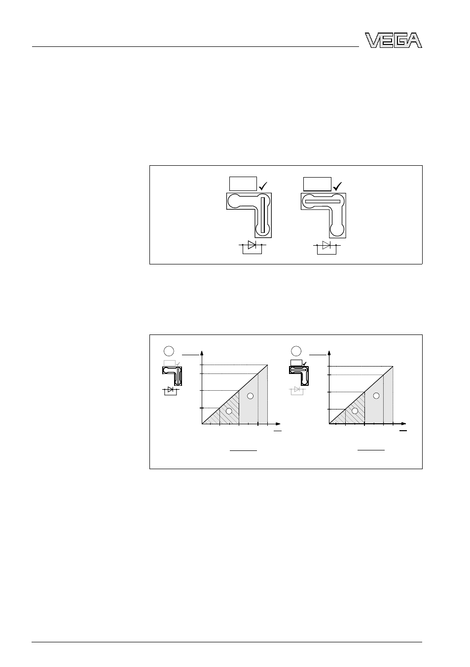
Test
Test
Fig. 28: Left: Position position of the bridge without test signal. Min. supply
voltage 10.5 V DC. Right: Position of the bridge with test signal. Min. supply
voltage 11.5 V DC.
5
.5 Load
1
2
≤
30
20
10,5
U
[V]
40
45
1282
1500
847
413
Test
3
4
Ω
RLmax
RLmax
U - 10,5 V
23 mA
[ ]
30
20
11,5
U
[V]
40 45
1239
1456
804
369
Test
3
4
≤
RLmax
U - 11,5 V
23 mA
Ω
RLmax
[ ]
Fig. 29: Load diagrams: Note position of the bridge and flame proofing. RLmax
max. load resistance, U voltage supply
1
Bridge for 4 … 20 mA test signal plugged in position "Non-test"
2
Bridge for 4 … 20 mA test signal plugged in position "Test"
3
Voltage supply 10.5 (11.5) … 30 V DC for EEx ia, 1/2 D, 1 GD, 1/2 GD, FM
IS and CSA IS
4
Supply voltage 10.5 (11.5) … 45 V DC for instruments for Ex-free area, 1/
3
D, EEx d, EEx nA, FM XP, FM DIP, FM NI, CSA XP and CSA Dust-Ex
5
.6 Connection control
C
heck the following after electrical installation of the instrument:
l
D
oes the supply voltage correspond to the specification on the
type label?
30
VEGADIF
55 • 4 … 20
mA/HART
5 C
onnecting to power supply
31731
-EN
-081119