VEGA VEGACOM 558 Ethernet User Manual
Page 31
VEGACOM 558 Ethernet
31
10001
10002
10003
10004
10005
10006
10007
10008
10009
10010
10011
509
10510
510
10511
511
10512
10012
10013
10014
10015
10016
10017
1 BIT
Register
address
in
Modicon
Output 9
Values of
VEGALOG
Card on
module =
1
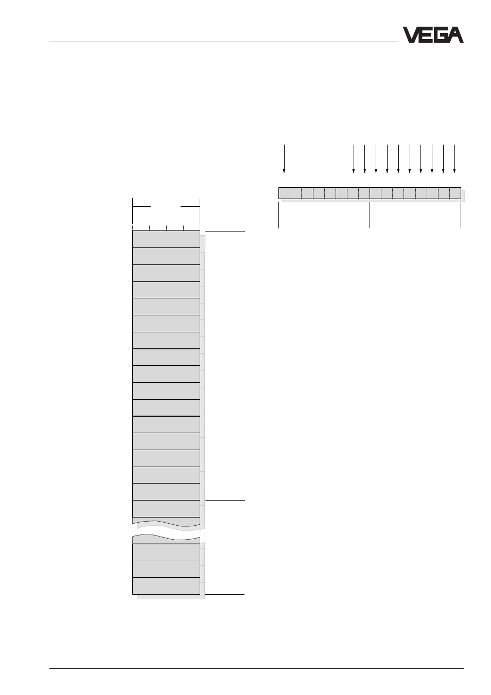
Addressing of the switching status in VEGACOM 558
for VEGALOG 571
Output 10
reserved
reserved
reserved
reserved
reserved
Status: Card
Output 1
Output 2
Output 3
Output 4
Output 5
Output 6
Output 7
Output 8
Output 9
Output 6
Output 7
Output 8
Values of
VEGALOG
Card on
module =
32
Status of the
output card
Switching status of output no:
Data image in VEGACOM 558
Addressing of the output status when
connected to LOGBUS
The image of the output status when
connecting to VEGALOG is always sorted
acc. to the module numbers of the output
cards, the following illustration shows the
addressing of the temporary memory via
Modbus.
If you image the 16 register bits belonging to
a module card as one 16 bit word, the
following graphical representation results:
The meaning of the individual bits is defined
as follows:
Status of the output card:
0 =
OK
1 =
no values of the output card available
(no outputs configured or card not
available)
Switching status of the inputs with AR or AT
cards:
0 =
relay deenergised
1 =
relay energised
Note:
A complete overview of the process image of
the switching status of VEGACOM 558 can
be found in supplement B at the end of this
operating instructions manual.
0
1
2
3
1
2
3
4
5
6
7
4
5
6
7
0
1
2
3
4
5
6
7
Bit
1.
Byte
2.
Byte
8
9
10
Temporary memory of
VEGACOM 558