Data image in vegacom 558 – VEGA VEGACOM 558 Ethernet User Manual
Page 24
24
VEGACOM 558 Ethernet
30001
30013
30015
30017
30019
30021
30023
30025
30027
30029
30031
30219
30221
30223
4 Byte
Register
address
in
Modicon
reserved
DCS output 1
DCS output 2
DCS output 3
DCS output 4
DCS output 5
DCS output 6
VEGAMET
with DISBUS
address 15
High-
Byte
Low-
Byte
Meas.
unit
Sta-
tus
Meas. value
Add. info
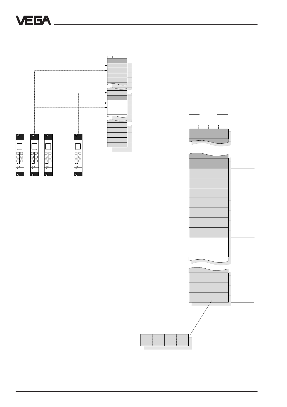
Organisation of the temporary memory for
VEGAMET 513, 514, 515 or 614 signal condi-
tioning instruments
DCS output 7
reserved
DCS output 5
DCS output 6
DCS output 7
VEGAMET
with DISBUS
address 2
DCS output 1
DCS output 2
Addressing of measured values when
connected to DISBUS
With grouping acc. to VEGAMET address
(DCS 1 from MET 1, …)
Note:
A complete overview of the process image of
VEGACOM 558 can be found in supplement
A at the end of this operating instructions
manual
VEGAMET
with DISBUS
address 1
Grouping of measured values acc. to VEGAMET
addresses on VEGAMET 513, 514, 515 or 614
on
VEGAMET
513
!
ESC
OK
-
+
100
%
CONNECT
on
VEGAMET
513
!
ESC
OK
-
+
100
%
CONNECT
on
VEGAMET
513
!
ESC
OK
-
+
100
%
CONNECT
on
VEGAMET
513
!
ESC
OK
-
+
100
%
CONNECT
If the entry "DCS 1 from MET 1-15, …" is
activated, the measured values will be
grouped acc. to DCS indices or channels.
Grouping of measured values acc. to DCS indices or
channels
all DCS outputs with index =1
all DCS outputs with index =2
Data image in VEGACOM 558
Temporary memory
VEGACOM 558
Temporary memory
in VEGACOM 558