VEGA VEGACOM 558 Ethernet User Manual
Page 27
VEGACOM 558 Ethernet
27
10001
10002
10003
10004
10005
10006
10007
10008
10009
10010
10011
10238
10239
10240
10012
10013
10014
10015
10016
10017
10018
10019
1 BIT
Register
address
in
Modicon
Input contact 2
VEGAMET
with
DISBUS
address =
1
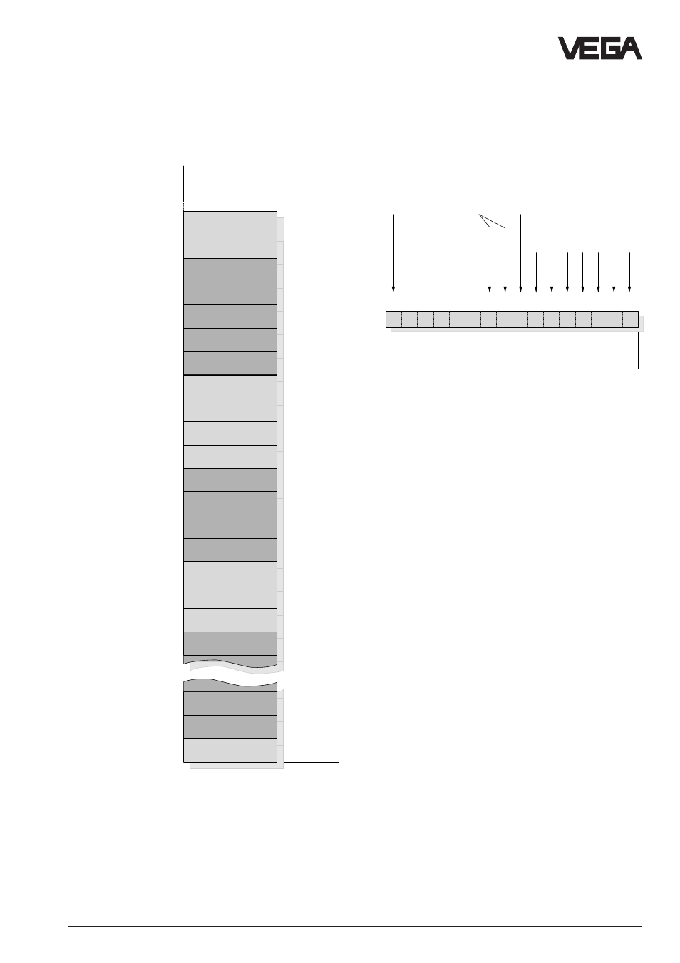
Addressing of the switching conditions in VEGACOM
558 for VEGAMET 513, 514, 515 or 614
Input contact 1
reserved
reserved
reserved
reserved
reserved
Status: Inputs
Relay contact 1
Relay contact 2
Fail safe relay
reserved
reserved
reserved
reserved
Status: Outputs
Input contact 2
Input contact 1
reserved
VEGAMET
with
DISBUS
address =
2
VEGAMET
with
DISBUS
address =
15
reserved
reserved
Status: Outputs
Status of
inputs
Switching
status of
input
no.:
Status of
outputs
Switching
status of
output no:
Data image in VEGACOM 558
Addressing of the switching conditions
when connected to DISBUS
If you imagine the 16 register bits belonging
to a VEGAMET as one 16 bit word, the
following graphical repesentation results.
The meaning of the individual bits is defined
as follows:
Status of inputs:
0 =
all inputs OK
1 =
input status not available (no inputs
configured or VEGAMET not available)
Switching status of inputs 1 and 2:
0 =
input contact is open
1 =
input contact is closed
Status of outputs:
0 =
all outputs OK
1 =
output status not available (no outputs
configured or VEGAMET not available)
Switching status of outputs 1, 2 and 3 (output
3 corresponds to fail safe relay):
0 =
relay is deenergised
1 =
relay is energised
Note:
A complete overview of the process images
on the switching status of VEGACOM 558
can be found in supplement B at the end of
this operating instructions manual.
0
1
2
3
1
2
3
4
5
6
7
0
1
2
3
4
5
6
7
Bit
1
2
1.
Byte
2.
Byte
Temporary memory in
VEGACOM 558