VEGA VEGACOM 558 Ethernet User Manual
Page 25
VEGACOM 558 Ethernet
25
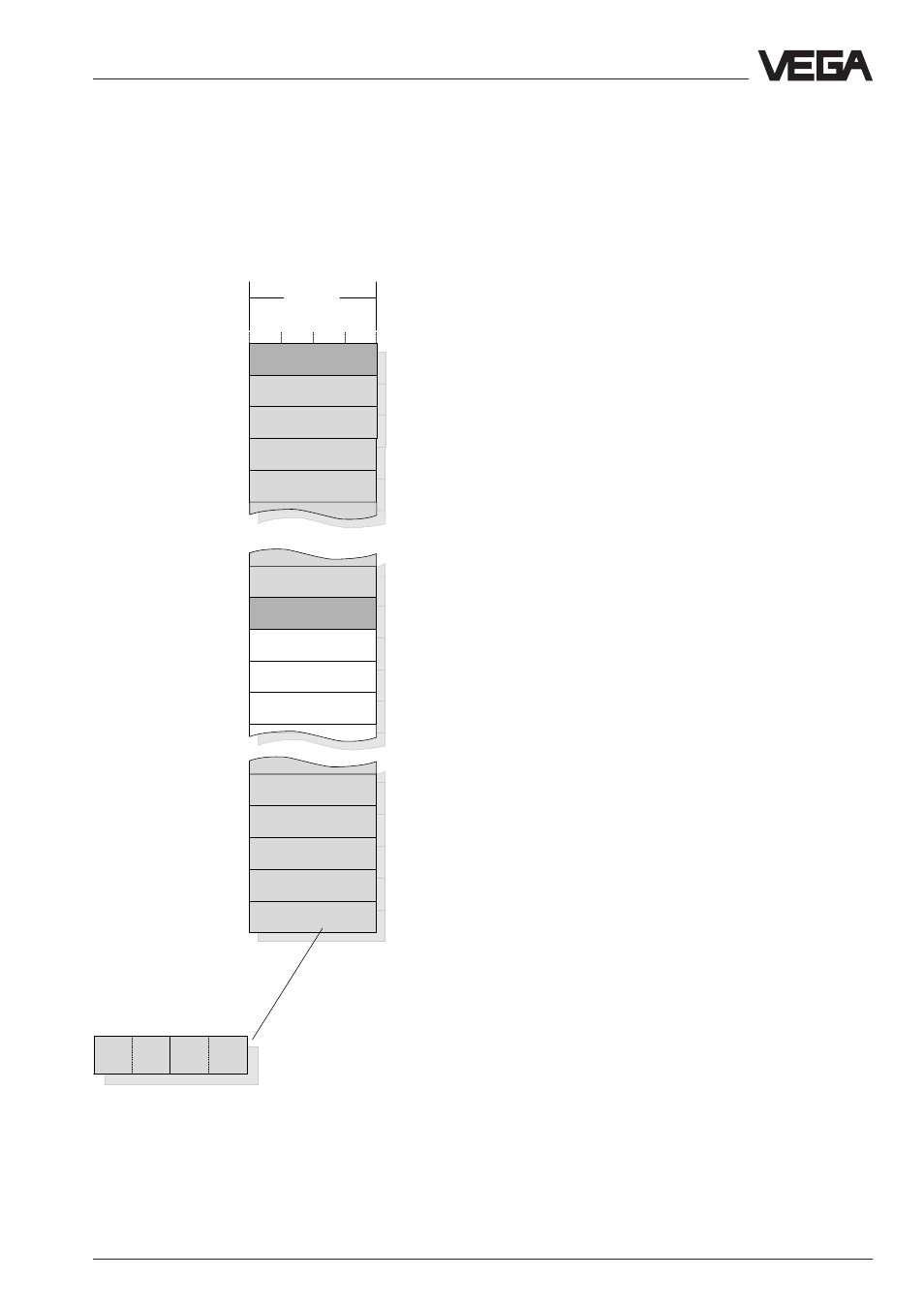
Organisation of the temporary memory for
VEGAMET 513, 514, 515 or 614 signal condi-
tioning instruments
30007
30009
30031
30033
30035
30037
30039
30219
30221
30223
30001
30003
30005
30215
30217
3
4
15
1
2
3
13
14
15
1
2
11
12
4 Byte
Register
address
in
Modicon
reserved
DCS output 1
DCS output 1
DCS output 2
VEGAMET
with
DISBUS
address =
DCS output 7
High-
Byte
Low-
Byte
Meas.
unit
Sta-
tus
Meas. value
Add. info
DCS output 1
DCS output 1
DCS output 1
reserved
DCS output 2
DCS output 2
DCS output 7
DCS output 7
DCS output 7
DCS output 7
Grouping acc. to DCS indices (DCS 1 from MET 1-15, … ):
Grouping of measured values acc. to DCS indices for
VEGAMET 513, 514, 515 or 614
Note:
A complete overview of the process image of VEGACOM 558 can be found in supplement A at
the end of this operating instructions manual
Data image in VEGACOM 558
Temporary memory in
VEGACOM 558