Vegacom 557 with vvo or vv – VEGA VEGACOM 557 Modbus protocol User Manual
Page 7
VEGACOM 557 Modbus
7
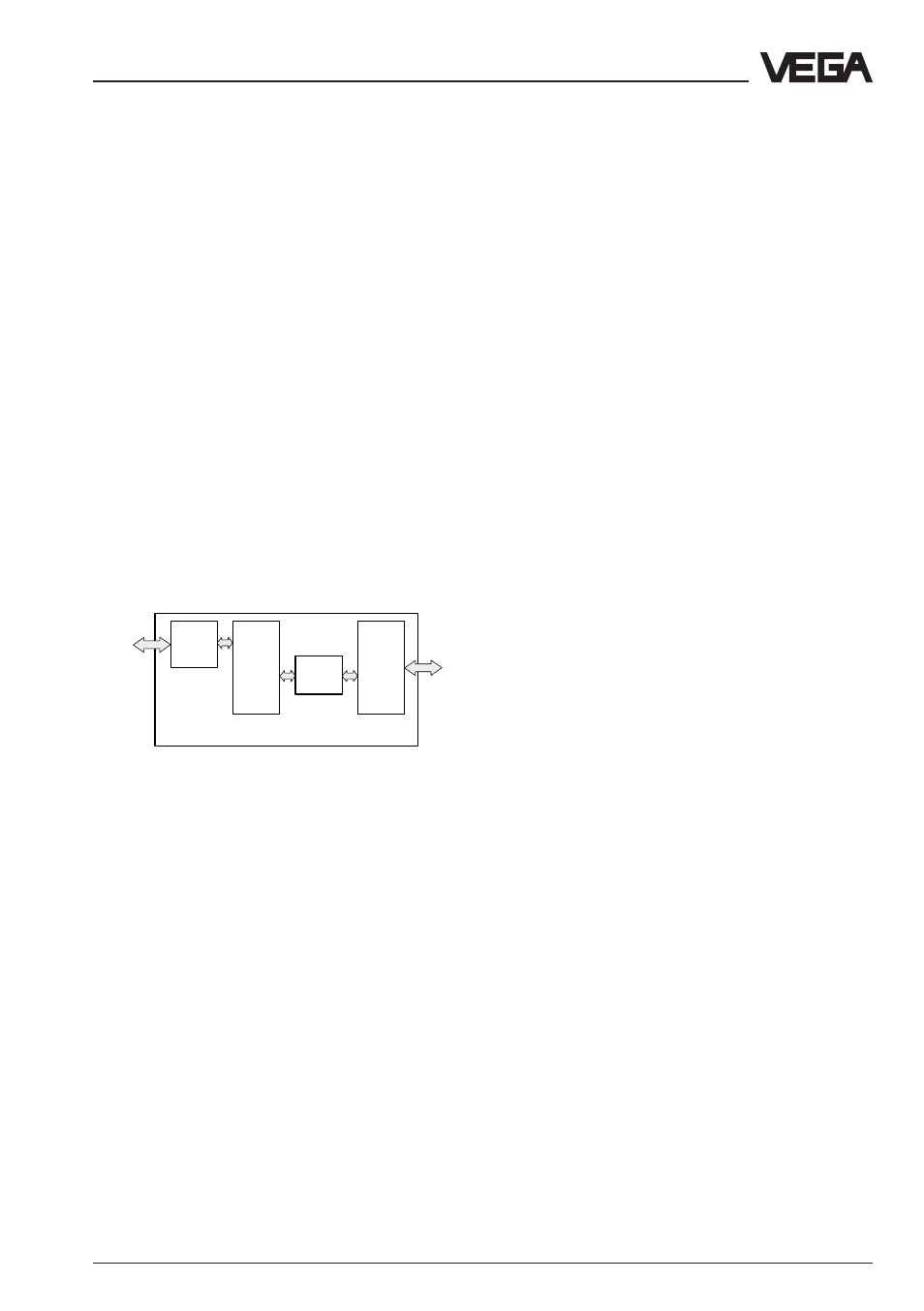
DISBUS
LOGBUS
Modbus
Function VEGACOM 557
Buffer
memory
Proc-
ess
image
Emis-
sion
memory
Test
conver-
sion
Product description
VEGACOM 557 on Modbus
The data communication between VEGACOM
557 and Modbus master is only carried out if
initiated by the master, which can enquire the
requested information by means of special
commands.
The data from DISBUS/LOGBUS are first
written in a buffer memory of VEGACOM 557.
The data set is transferred from this buffer
memory into a process image. The protocol
conversion software enquires the stored data
cyclically from the individual storage areas.
The data sets are checked and converted
into the Modbus data format. After the con-
version, the data are transferred into the
emission memory and are sent from there to
the Modbus. The Modbus transmits the data
to the DP-Master.
VEGACOM 557 with VVO or VV
Direct connection
As an alternative to the Modbus communica-
tion, a PC can be connected via the PC inter-
face (SUB-D-plug in the front panel of
VEGACOM 557). By means of the adjustment
and indicating software VEGA Visual Opera-
ting (VVO), the parameter adjustment can be
made on the signal conditioning instruments
connected to VEGACOM 557. The VEGA
adjustment concept includes the user-friendly
configuration and parameter adjustment of
the measuring system or the sensor with the
following instruments:
- VEGAMET series 500/600 signal condi-
tioning instruments
- VEGALOG 571 processing system
- VBUS ultrasonic/radar sensors.
The adjustment is menu-driven and window
oriented. No matter if a radar sensor, several
connected signal conditioning instruments or
a VEGALOG should be adjusted via the PC,
the procedure is always the same. As an-
other possibility, measured values and fault
signals of the entire processing facility can
be recorded and shown graphically by
means of the visualisation software VISUAL
VEGA (VV). Tools for processing and analy-
sis of history data are also available.
The configuration of the measurement loop
comprises, depending on the connected
instruments, e.g. the determination of output
functions or the configuration of individual
outputs or inputs. The user-orientated editing
of measurement loops is supported by
graphic means, such as e.g. vessel draw-
ings and pictographs that adapt to the se-
lected general conditions and options.
Thanks to graphic support, more complex
parameter adjustments such as e.g., the
input of a linearisation curve by means of
index markers, can also be done with ease.
Connection via modem
The PC interface supports, beside the direct
connection of a PC, also the operation via
modems. With this additional function, remote
parameter adjustment or remote diagnostics
of VEGA systems via VVO are possible.
Together with the visualisation software Visual
VEGA, even remote visualisations can be
carried out.