D b z, Mounting and electrical connection – VEGA VEGACOM 557 Modbus protocol User Manual
Page 17
VEGACOM 557 Modbus
17
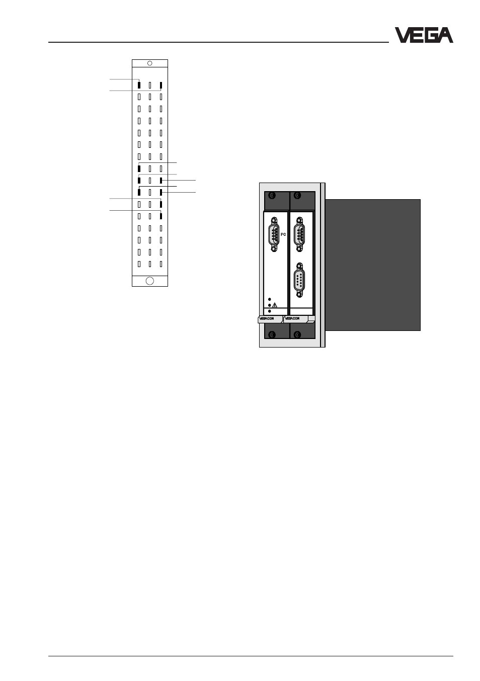
Supply voltage
GND
DISBUS (not
used on VEGA-
LOG)
Modbus via TTY
–
T+
R-
+
–
+
Wiring regulation for Modbus connection via TTY
TTY
TTY
TTY
TTY
d b z
10
8
6
4
2
12
14
16
18
20
22
24
26
28
30
32
R+
T-
Mounting and electrical connection
2.4 Mounting and installation in-
structions with VEGACOM 557AP
As an option, VEGACOM 557 can be ex-
tended with the adapter print VEGACOM
557AP. The adapter print VEGACOM 557AP
consists of a module card with 5 TE width
and two modules connected to a back-panel
print for carrier BGT 596 or BGT LOG 571.
With the adapter print card it is possible to
put the Modbus interfaces of VEGACOM 557
at the front of the carrier. On the front of the
adapter print card, the Modbus interface is
available as a 9-pole SUB-D-plug and as 9-
pole SUB-D-socket. The required interface
type must be stated when ordering VEGA-
COM 557AP.
The following interface types are available::
- RS 232
- RS 422
- RS 485
- TTY
Make sure that also VEGACOM 557 is set to
the same interface type (DIL-switch 1 on the
additional board) as VEGACOM 557AP. The
pin assignments of SUB-D-plug and SUB-D-
socket are listed in the tables.
VEGACOM 557 with adapter print VEGACOM 557AP
557
557AP
on
BA