4 data image in vegacom 557, 1 image of measured value when connected to disbus, Data image in vegacom 557 – VEGA VEGACOM 557 Modbus protocol User Manual
Page 24: All measured values of vegamet #2
24
VEGACOM 557 Modbus
on
VEGAMET
513
!
ESC
OK
-
+
100
%
CONNECT
on
VEGAMET
513
!
ESC
OK
-
+
100
%
CONNECT
on
VEGAMET
513
!
ESC
OK
-
+
100
%
CONNECT
on
VEGAMET
513
!
ESC
OK
-
+
100
%
CONNECT
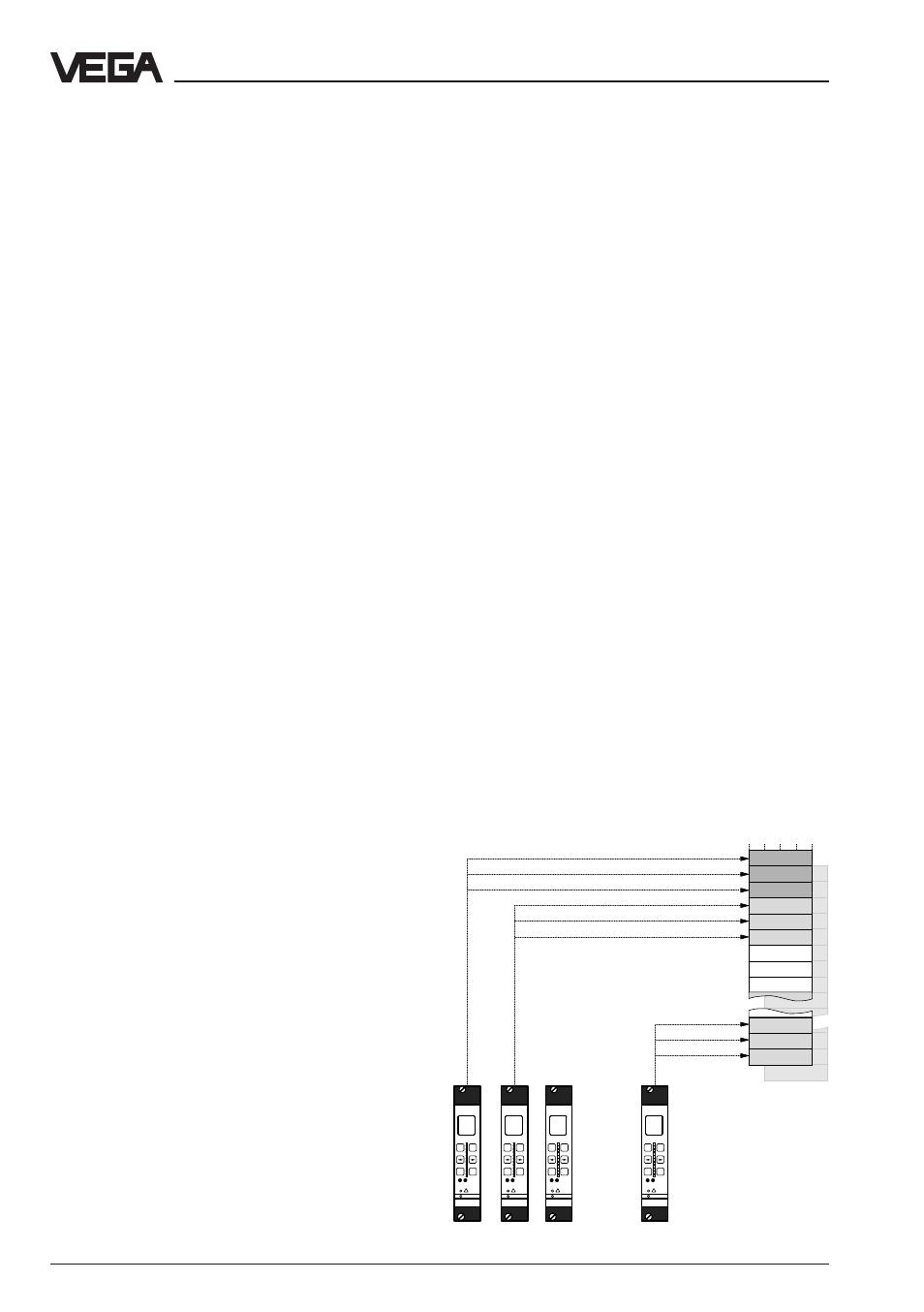
Data image in VEGACOM 557
all measured values
of VEGAMET #2
VEGACOM 557 collects the measured values
of the VEGA signal conditioning instruments
VEGAMET 509, 512, 513, 514, 515 and 614
(via DISBUS) or VEGALOG 571 (via LOG-
BUS) and puts them in the temporary
memory for collection via the Modbus. The
method of storing the measured values (for
the higher-priority processing system) in the
VEGACOM 557 temporary memory differs
depending on the selected configuration. It
depends on whether VEGACOM 557 is con-
nected to the DISBUS or the LOGBUS, and if
DISBUS, also on the connected instrument
type. However, it can also be modified by
VEGACOM 557 itself via DIL switches.
Note
On the VEGAMET 513, 514, 515 and 614
signal conditioning instruments, as well as on
the VEGALOG 571 processing system, the
individual configuration of the DCS outputs
with the adjustment software VVO is possi-
ble.
On VEGAMET 513, 514, 515 and 614 signal
conditioning instruments as well as the VE-
GALOG 571 processing system, it is addi-
tionally possible to enquire the conditions of
the contact inputs/ and outputs via VEGA-
COM 557.
The enquiry of the measured value is made
through:
- Function code 04 (= Read Input Registers)
The enquiry of the switching conditions is
made through:
- Function code 01 (= Read Coil Status) or
alternatively through
- Function code 02 (= Read Input Status).
For further details on the handling of the
function codes 01, 02 and 04 see chapter
"5 Setup“.
Grouping of measured values acc. to VEGAMET-
addresses
all measured values
of VEGAMET #15
all measured values
of VEGAMET #1
4.1 Image of measured value when
connected to DISBUS
The addressing of the measured values for
Modbus systems is "word-orientated“. In
VEGACOM 557 one measured value is rep-
resented by two words, the first word con-
tains the real measured value, the next higher
word the respective status information. In the
standard, “register word” is used instead of
the term “word”. The addressing is made
either through existing library enquiries of a
PLC (e.g. Modicon) or by direct generation of
the Modbus telegrams. Examples of valid
register word addresses are shown in the
following illustration. Especially when using
Modicon, make sure that, for the library en-
quiry, the register address is increased by 1
with respect to the transmitted address on
the Modbus.
As already mentioned, the storage of the
measured values for VEGAMET signal condi-
tioning instruments can be influenced by the
user. Switch 1 of DIL-switch block 2 is deci-
sive. If switch 1 is set to position "OFF“, the
measured values are grouped acc. to the
VEGAMET addresses in ascending se-
quence.
4 Data image in VEGACOM 557