VEGA VEGACOM 557 Modbus protocol User Manual
Page 26
26
VEGACOM 557 Modbus
0
30001
2
30003
4
30005
6
30007
8
30009
10
30011
12
30013
14
30015
16
30017
90
30091
92
30093
94
30095
4 Byte
0
30001
12
30013
14
30015
16
30017
18
30019
20
30021
22
30023
24
30025
26
30027
28
30029
30
30031
218
30219
220
30221
222
30223
4 Byte
Register
address
in
Modicon
reserved
reserved
reserved
Meas. value channel 1
Meas. value channel
2
Meas. value channel 3
Meas. value channel1
Meas. value channel2
Meas. value channel 3
VEGAMET
with DISBUS
address 1
Meas. value channel1
Meas. value channel2
Meas.value channel3
VEGAMET
with DISBUS
address 2
VEGAMET
with DISBUS
address 15
High-
Byte
Low-
Byte
Unit
Sta-
tus
Meas. value
Add. info
Register
address in
VEGA-
COM 557
Register
address
in
Modicon
reserved
DCS output 1
DCS output 2
DCS output 3
DCS output 4
DCS output 5
DCS output 6
VEGAMET
with DISBUS
address 15
High-
Byte
Low-
Byte
Unit
Sta-
tus
Meas. value
Add. info
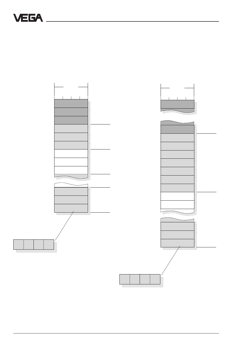
Case 2:
There are only instruments of type VEGAMET
513, 514, 515 or 614 connected.
Register
address in
VEGA-
COM 557
DCS output 7
reserved
DCS output 5
DCS output 6
DCS output 7
VEGAMET
with DISBUS
address 2
DCS output 1
DCS output 2
Addressing of measured value when connected to DISBUS with grouping acc. to
VEGAMET address (switch 1 of DIL switch block 2 is in position OFF):
Case 1:
There are only instruments of type VEGAMET
509 or 512 connected.
Note:
A complete overview of the process image of VEGACOM 557 can be found in supplement A
at the end of this manual.
Grouping of measured values acc. to VEGAMET
addresses on VEGAMET 509 or 512
VEGAMET
with DISBUS
address 1
Grouping of measured values acc. to VEGAMET
addresses on VEGAMET 513, 514, 515 or 614
Data image in VEGACOM 557