2 mounting and electrical connection, 1 mounting instructions, Coding – VEGA VEGACOM 557 Modbus protocol User Manual
Page 14
14
VEGACOM 557 Modbus
d b z
1
a c
3
c3
c11
a27
5
7
9
15
17
19
21
23
25
27
11
13
29
31
VEGALOG card
Interface card
VEGACOM 557
2 Mounting and electrical
connection
2.1 Mounting instructions
The gateway VEGACOM 557 can process
measured data and status information in two
different ways:
- via DISBUS (from measuring systems with
VEGAMET)
- via LOGBUS (from measuring systems
with VEGALOG).
For DISBUS configurations, VEGACOM 557
can be either mounted into carrier BGT 596
or housing type 505.
In conjunction with LOGBUS, VEGACOM 557
is mounted into carrier BGT LOG 571. The
location is individually selectable, the system
adapts automatically when rebooting
(autoconfiguation).
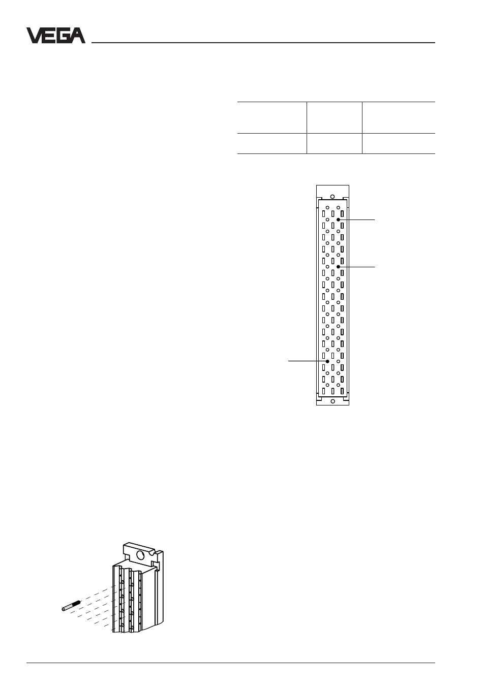
Coding
A mechanical coding system prevents mixing
up the different module cards in the carrier or
in the housing.
The coding system consists of:
- three coded pins in the multipoint connec-
tor
- three holes in the multiple plug of VEGA-
COM 557.
The coded pins are attached to the module
or the housing. The plug-in socket must be
equipped by the user with the coded pins
according to the following table and diagram.
Instrument coding
Function coding
Coded pin
Plug-in socket of VEGACOM 557
Positioning of the coded pins
Mounting and electrical connection
Instrument
Function
coding
coding
VEGACOM 557 a27
c3/c11