4 image of the contact outputs on logbus – VEGA VEGACOM 557 Modbus protocol User Manual
Page 32
32
VEGACOM 557 Modbus
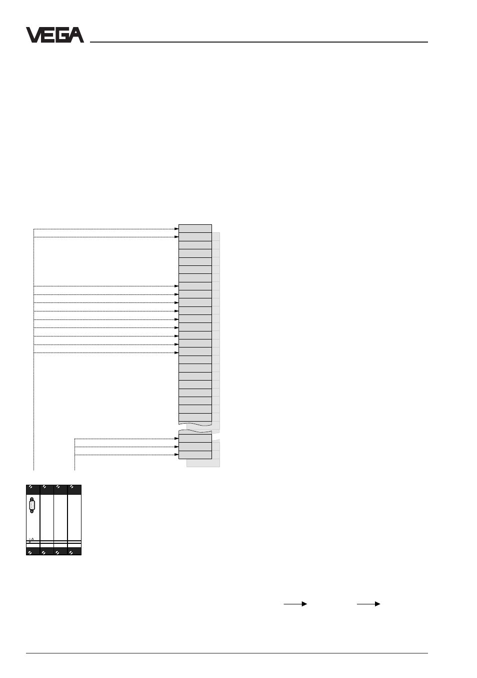
4.4 Image of the contact outputs on
LOGBUS
Beside the previously described measured
values, it is also possible to transmit the
switching status of VEGA processing system
VEGALOG 571 through VEGACOM 557.
These are:
- status of the contact output of the AR cards
(relay contacts)
- status of the contact outputs of the AT
cards (transistor outputs)
In contrast to the image of measured values,
the image of the switching status is made "bit
orientated“. In the standard, these status bits
are also called “register bits”. The address-
ing of the register bits for Modbus systems is
therefore made "bit orientated“. In VEGACOM
557, a switching status is represented by a
register bit, whereby all available information
of a VEGALOG output card of type AR or AT
is saved within a related block of 16 register
bits. The storage of a 16 register bit block
within VEGACOM 557 results from the mod-
ule position in VEGALOG 571.
The addressing by the guidance system is
made either via existing library enquiries of a
processing system (e.g. Modicon) or by direct
generation of the Modbus telegrams.
Please keep in mind that the number of regis-
ter bits to be enquired per telegram should
always be divisible by 8.
For enquiry of the switching status, the func-
tion codes 01 or 02 can be used on VEGA-
COM 557 for input and output status.
Note:
When addressing register bits, all addresses
between 0 and 65 535 can be used with
VEGACOM 557. For accessing the intermedi-
ate storage area, VEGACOM 557 uses gen-
erally only the last 3 digits of the address.
This means:
Register
Register
Register
address in
address on
address in
Modicon
Modbus
VEGACOM
557
00 001
00 000
000
10 017
10 016
016
04 001
04 000
000
14 017
14 016
016
Image of switching status in VEGACOM 557 on VEGA-
LOG 571
on
PC
VEGALOG
571
!
Output status of output card on
module #1
Output status of output
card on module #32
Data image in VEGACOM 557