Connections of the multiple plug (rear), D b z – VEGA VEGACOM 557 Modbus protocol User Manual
Page 16
16
VEGACOM 557 Modbus
d b z
10
8
6
4
2
12
14
16
18
20
22
24
26
28
30
32
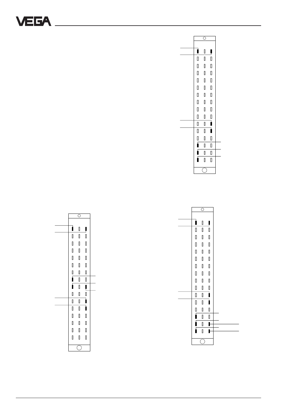
Supply voltage
GND
DISBUS (not
used on VEGA-
LOG)
Modbus via
RS 232 C
–
TxD
RxD
+
–
+
Wiring regulation for Modbus connection via
RS 232 C
RS 232 C
RS 232 C
RS 232 C
RS 232 C
Supply voltage
GND (C/C´)
DISBUS (not
used on VEGA-
LOG)
Modbus via
RS 485
–
DATA (B/B´)
/DATA (A/A´)
+
–
+
Wiring regulation for Modbus connection via RS 485
RS 485
RS 485
RS 485
RS 485
Supply voltage
GND
DISBUS (not
used on VEGA-
LOG)
Modbus via
RS 422
–
RX
/RX
+
–
+
Wiring regulation for Modbus connection via RS 422
RS 422
RS 422
RS 422
RS 422
d b z
10
8
6
4
2
12
14
16
18
20
22
24
26
28
30
32
d b z
10
8
6
4
2
12
14
16
18
20
22
24
26
28
30
32
TX
/TX
Mounting and electrical connection
Connection via modem
For remote parameter adjustment, it is possi-
ble to connect the PC interface via a modem.
In such a case, the modem cable that comes
with the respective modem should be used.
Modem operation is supported by VEGA-
COM 557 from software version 2.11. Further
information on the remote parameter adjust-
ment is stated in the operating instructions
"Remote parameter adjustment“.
Connections of the multiple plug (rear)
For connection of VEGACOM 557 to the ex-
isting Modbus system, all standard inter-
faces are available. The power supply of the
instrument and the connection to the VEGA
system remain always the same. The follow-
ing illustrations show the respective terminal
assignments of the Modbus depending on
the selected interface type.