Cable connections – Ohaus CT Series ELECTRONIC BALANCE User Manual
Page 83
3
7.
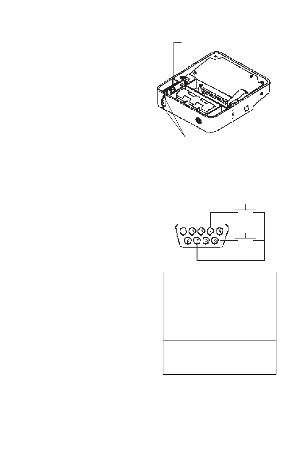
Place the RS232 circuit board and
connector assembly in the balance
so that the 9-pin connector fits through
the hole.
8.
Fasten the Interface assembly to the
balance using the two screws pro-
vided with the Interface.
9
Replace the bottom plate and fasten
with the 4 screws previously removed.
10. Install the batteries (if removed) or
AC Adapter.
11. Replace the platform.
Cable Connections
Cable Connections
Cable Connections
Cable Connections
Cable Connections
It is recommended to use an Ohaus cable,
however, you may configure your own.
On the rear of the balance, a 9-pin submin-
iature “D” connector is provided for inter-
facing to other devices. The pinout and pin
connections are shown in the adjacent
illustration.
The balance will not output any data un-
less pin 5 (CTS) is held in an ON state (+3
to +15 V dc). Interfaces not utilizing the
CTS handshake may tie pin 5 to pin 6 to
defeat it.
Connect the cable from the balance to the
external device.
If communication parameters of the exter-
nal device match the factory settings, the
Interface is ready for use. Refer to Print-
ing. If not, refer to Configuring the Print
Menu to change the interface parameters.
INSERT CIRCUIT BOARD
AS SHOWN
FASTEN SCREWS
1
Make no connection
2
Data Out (TXD)
3
Data In (RXD)
4*
Tare (External signal)
5
Clear To Send (CTS)
6
Data Terminal Ready (DTR)
7
Ground
8
Request To Send (RTS)
9*
Print (External signal)
* External PRINT and/or TARE
switches may be installed as shown
in the diagram. Momentary con-
tact switches must be used.
PRINT *
TARE *