Supply connections, Hose connections, Figure 3 – M&C TechGroup CSS-M Operator's manual User Manual
Page 11: Hose connections css-m portable
4-2.1.3-ME
Gas sampling and gas conditioning technology
11
12
SUPPLY CONNECTIONS
12.1
HOSE CONNECTIONS
220
177
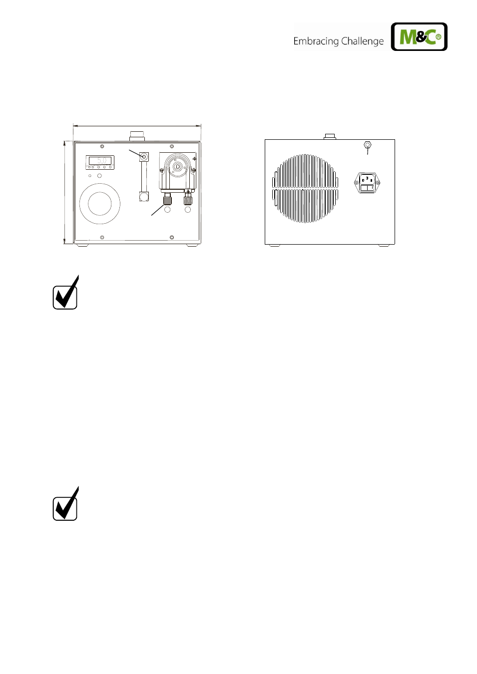
Sample gas outlet
Condensate outlet
0
Sample gas inlet
Figure 3
Hose connections CSS-M portable
N O T E !
Do not mix up the hose connections; the connections are marked
accordingly in figure 3.
After having connected all lines, please check the seals.
All hose connections are DN4/6mm sealing ring threaded hose couplings out of PVDF/PPH as
standard. They are suitable for gas inlet temperatures of maximum 80°C (see chapter 8).
The mounting of the sample gas hoses and the condensate hoses is to be executed as follows:
Remove the union nut from the sealing ring couplings by turning it anti-clockwise. The nut should
be removed from the thread with great care so as to ensure that the loose sealing ring in the nut is
not lost.
Place the union nut over the connecting hose.
Push the sealing ring over the connecting hose with the thicker bead towards the nut.
Place the hose over the nipple on the thread.
N O T E !
The tightness of the connections can only be guaranteed if the connecting
hose has a straight edge (use a hose cutter).
The union nut is to be screwed tight by hand.
The hose will no longer be able to slip off, and is now compression-proof.
The hoses are to be removed in the reverse order.