M&C TechGroup PMA 20 Operator's manual User Manual
Page 20
20
Gas sampling and gas conditioning technology
9-3.5.1-ME
Connect the hose end of the instrument air or check gas bottle connection to the gas inlet
of the analyser.
Open the pressure reducer valve slowly, to avoid pressure peaks.
Adjust the flow rate to 50 Nl/hr at the flow meter.
N O T E !
Always calibrate at the flow rate that is adjusted for the measurement
too.
Wait approximately 20
– 30 sec. until the indication has stabilised.
If necessary adjust span accurately according to the check gas concentration with a screw
driver at the span potentiometer in the front panel. In case of air e.g. to 20,9 % O
2
.
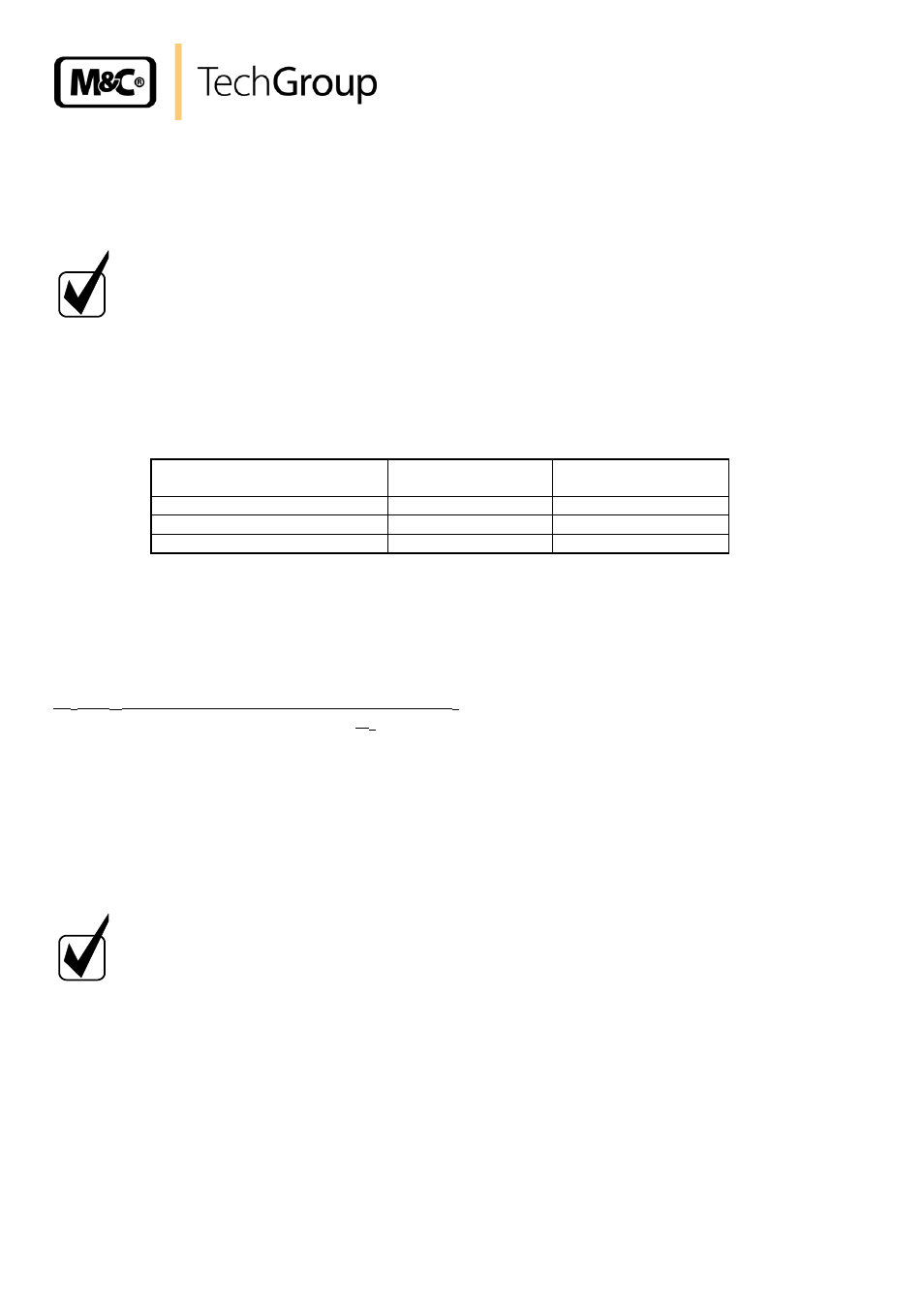
Check output signals at 20,9% O
2
:
Shut off pressure reducer valve and bottle- resp. Instrument air valve resp. integrated
sample gas pump.
Disconnect hose connection at the analyser.
Determination of the output signal:
(S
e
– S
np
) V resp. mA x gas concentration Vol % O
2
upper range value Vol % O
2
Se = Final value, signal output
Snp = Zero, signal output
Shut off pressure reducer output valve and bottle valve. Druckreglerausgangsventil und
Flaschenventil schließen. Disconnect hose connection at the analyser.
The span calibration is finished.
N O T E !
If during the span calibration great variations have to be compensated
(>2% O
2
) at the potentiometers, a second zero and span calibration is
reasonable.
A T T E N T I O N
After finishing the calibration turn measuring selection switch to the
desired measuring range.
The mA-output signal is dependant on the measuring range!
Output signal
Measurement
range 100 % O
2
Measurement
range 30 % O
2
0-1 V
0,209 V
0,697 V
0-20 mA
4,18 mA
13,93 mA
4-20 mA
7,34 mA
15,15 mA
+ S
np