Standard gas conditioning system, Figure 5 – M&C TechGroup PMA 20 Operator's manual User Manual
Page 13
13
Gas sampling and gas conditioning technology
9-3.5.1-ME
12.1
CONNECTION OF SAMPLE GAS INLET AND SAMPLE GAS OUTLET
The sample gas inlet and outlet are placed at the bottom side of the analyser and have tube con-
nections DN4/6mm.
Connect the sample gas inlet (rear connection) with a corresponding gas conditioning with
e.g. a PTFE hose DN4/6.
A T T E N T I O N
Avoid back pressure in the sample gas outlet because an increase of
pressure will distort the oxygen indication.
Do not bend the connection hoses.
13
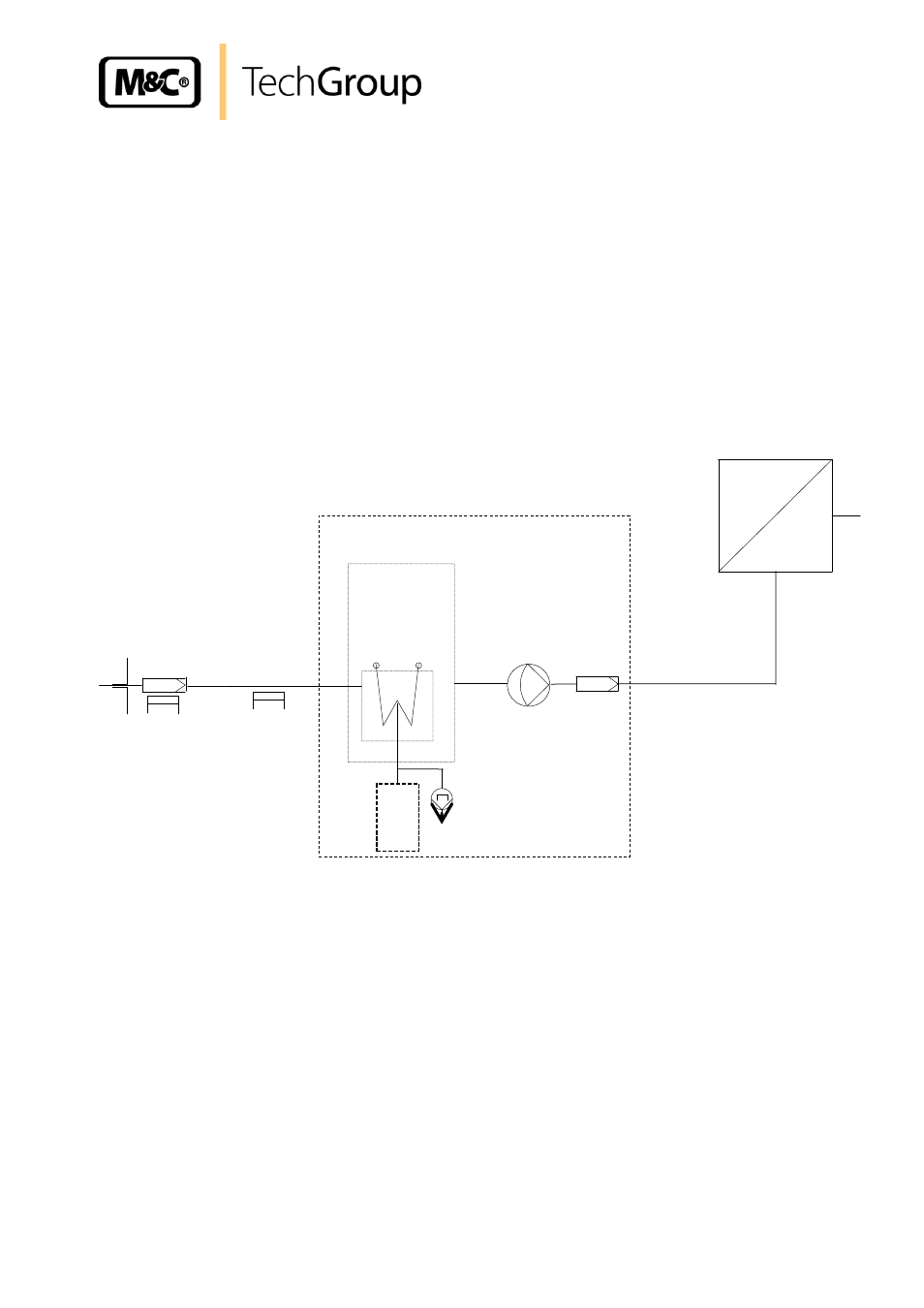
STANDARD GAS CONDITIONING SYSTEM
+5°C
PMA 20
Figure 5
Standard gas conditioning system
1 : Heated gas sample probe (e.g. probe SP2000-H)
2 : Heated gas sample line (e.g. 4M4/6)
3 : Sample gas cooler (e.g. ECM-1G)
4 : Peristaltic pump or condensate collecting vessel (e.g. SR25.1 or TG-1)
5 : Diaphragm pump (e.g. N3)
6 : Fine filter (FP-2T)
- SP10 Operator's manual (14 pages)
- N9 KP18 Operator's manual (21 pages)
- SP2000_20SS 150 Data sheet (3 pages)
- SP3100 Data sheet (6 pages)
- PSP4000-H _C _T Data sheet (4 pages)
- SP2200-H_C_I_BB_F Data sheet (2 pages)
- SP35-H... for gas sample probe SP2000-H... Data sheet (2 pages)
- FP-BF Data sheet (2 pages)
- SP3200 Operator's manual (28 pages)
- FPF-0,1 Operator's manual (2 pages)
- PSS-10_1 Operator's manual (23 pages)
- CSS-V2 Data sheet (3 pages)
- PMA 50 EEX Operator's manual (48 pages)
- MP30 Operator's manual (18 pages)
- SP2600-H_C_I_BB_F_0,1GF190 Data sheet (3 pages)
- SR25.1_Ex Operator's manual (22 pages)
- PMA 10S Operator's manual (27 pages)
- CSS-M_W Data sheet (3 pages)
- PAS-500 Operator's manual (20 pages)
- SP2000H320_DIL... Data sheet (3 pages)
- SP3200 Data sheet (6 pages)
- FA-1_2_3,bi Operator's manual (24 pages)
- SR25 Data sheet (2 pages)
- SP3000 Data sheet (4 pages)
- PAS Series Data sheet (2 pages)
- CG Series Data sheet (2 pages)
- ECP 20-2 Data sheet (3 pages)
- MP30-EX Data sheet (2 pages)
- PSP4000-H_C_T Operator's manual (24 pages)
- DIL-U Data sheet (2 pages)
- ADS-So Data sheet (2 pages)
- VC-2-SL Operator's manual (18 pages)
- ECM-ExII Operator's manual (39 pages)
- MP12 Operator's manual (17 pages)
- FPF+ Data sheet (2 pages)
- KS 2.Ex Operator's manual (17 pages)
- PMA 50 EEX Data sheet (3 pages)
- PMA 10S Data sheet (3 pages)
- Gas Sample Probes Series SP Data sheet (2 pages)
- BA-C Operator's manual (16 pages)
- MV3_2-H Series Operator's manual (18 pages)
- VC-2-SL Data sheet (3 pages)
- FM-200K-H_FA Operator's manual (16 pages)
- SP 30-H.._EX2 Operator's manual (16 pages)
- SP2006-H280_DIL Operator's manual (35 pages)