Description, Figure 1, Flow characteristcs – M&C TechGroup FT-...-H2 Operator's manual User Manual
Page 9: 8description
9
Gas sampling and gas conditioning technology
5-2.1.1-ME
8
DESCRIPTION
The universal-filter out of PTFE with integrated filter elements (fineness 3 or 0,1 µm) is placed in an
electrically heated 2-part aluminium construction.
The temperature is controlled by an integrated compact capillary sensor thermostat with an excess
temperature limit switch with reset key at +30°C above T
set
and an alarm function for low temperature
alarm at -30°C below T
set
with voltage free status-alarm contact. The thermostat as well as the
electrical terminals are placed in the junction box.
The temperature of the filter is shown on a thermometer. For isolation and protection reasons, the
heated filter part is covered with a cap.
To prevent heating-interruptions, the in- and outlet connection area is heated too. The clamps are
fixed in order to support the sample lines.
The filter in- and outlet can be turned 180° on the oven top position to achieve easy mounting and
flexible adaptation to local circumstances.
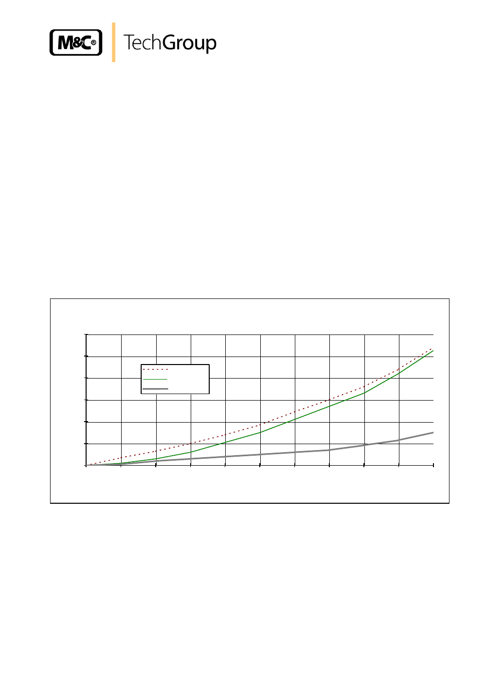
The following diagram illustrates the differential pressures of the different filter element materials in
dependance on the gas flow.
differential pressure in mbar with clean filter elements
0
10
20
30
40
50
60
0
50
100
150
200
250
300
350
400
450
500
air flow in l/hr at 20°C
d
if
fe
re
n
ti
a
l
p
re
s
s
u
re
m
b
a
r
FT-3SS-H2
FT-3G-H2
FT-0,1GF-H2
Figure 1
Flow characteristcs