Electrical connections, Figure 5, Terminals for mains supply and temperature alarm – M&C TechGroup ECP20-2 Operator's manual User Manual
Page 14
14
Gas sampling and gas conditioning technology
3-1.10-ME
12.2
ELECTRICAL CONNECTIONS
W A R N I N G !
When connecting the equipment, please ensure that the supply
voltage is identical with the information provided on the model
type plate.
N O T E !
For the erection of power installations with rated voltages up to
1000V, the requirements of VDE 0100 and relevant standards and
specifications must be observed!
Set the voltage selector S1 to the correct mains voltage!
The main circuit is equipped with a fuse corresponding to the
nominal current (over current protection); for electrical details see
technical data.
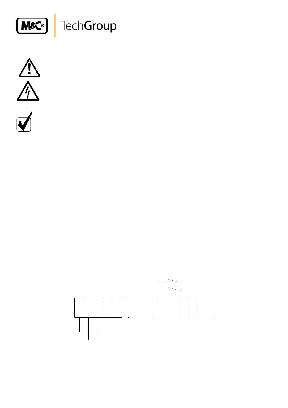
The main power supply terminals are located in the aluminium enclosure on the ECP 20... electronic
board:
Power On, Terminal X1: 1, 2, 3 / L, N, PE
Coolers from serial nos.: 95.. also have a mains selector (S1) on the basic board for either 230V 50Hz
or 115V 60Hz operation on the basic circuit board (see circuit diagram in appendix).
Before commissioning, use a screwdriver to turn the selector to the correct position 230/115
depending on your main power input supply.
The status alarm contact for indicating and isolating the gas supply must be incorporated into the
equipment control system.
The volt free contact outputs of the status group alarm is located on the ECP 20.... control board:
Temp. Alarm Terminal X2: 1 and 3 normal opened, 2 and 4 normal closed.
The two PG11 cable glands are located on the underside of the cooler enclosure. For further details
refer to the electrical circuits and terminal drawing and cover plate.
1
L
2
N
4
PE
3
PE
5
L
6
N
1
2
3
4
X1
X2
Netz/Power
230V/115V
50Hz/60Hz
ECP20/1 150VA
ECP20/2 250VA
Alarm
250V AC
2A
500VA
ECP20/1, ECP20/2
Sicherung F1 4,0 A
T
Fuse F2 4,0 A
T
Figure 4
Terminals for mains supply and temperature alarm