Description, Figure 2, Ec-ex cooler – M&C TechGroup EC-EX Operator's manual User Manual
Page 10: 11 description
10
Gas sampling and gas conditioning technology
3-4.1ME EC-EX 9904
11
DESCRIPTION
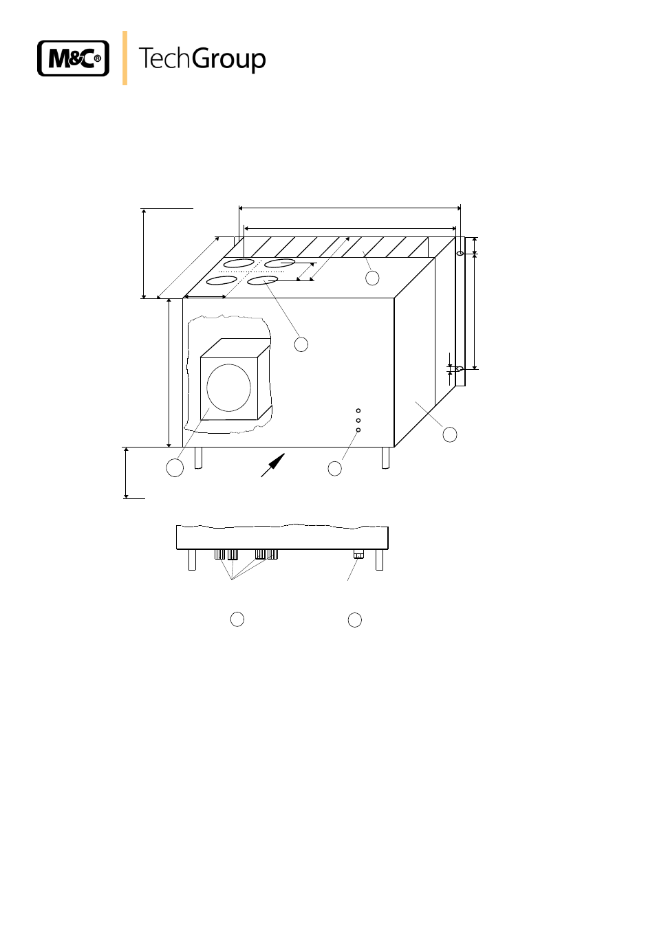
Figure 2 shows the EC-EX cooler unit .
°C>
ON
°C<
A
235
310
435
1
2
4
3
37,5
6,2
* necessary locating distance
240
70
85
88 * 2HE
100 *
7 HE
465
84 TE
View A
2 X cable glands
PG 13,5
max. 4 X condensate out
6
7
450
5
Figure 2 EC-EX cooler
The EC-EX
is equally suitable for wall installation or mounting in a 19“ rack.
The versions differ in the positioning of the LED function display . While for wall installation the LED
function display can be fitted into the corresponding cut-outs in the EC-EX
front panel, for 19” rack
mounting this is done using the cut-outs in the back panel of the casing. This positioning can be done
at the factory by when stating the type of installation of the EC-EX gas cooler. It is relatively simple to
subsequently reconfigure it on site at the user location. The location for installation of the LED function
display will be marked correspondingly.
The casing depth of the EC-EX cooler is 450mm. Additio
nal installations within the casing aren’t
possible.
The electrical parts of the cooler EC-EX are explosion protected. The EC-EX control board and the
protective motor switch are mounted in a flameproof enclosure EEx-d .