Pneumatic, Figure 8, Electrical connection of the pump – M&C TechGroup MP47_D Operator's manual User Manual
Page 15
15
Gas sampling and gas conditioning technology
6-1.1.1-ME
The pump must be installed so that contact with live parts (connections, possibly windings) is
impossible.
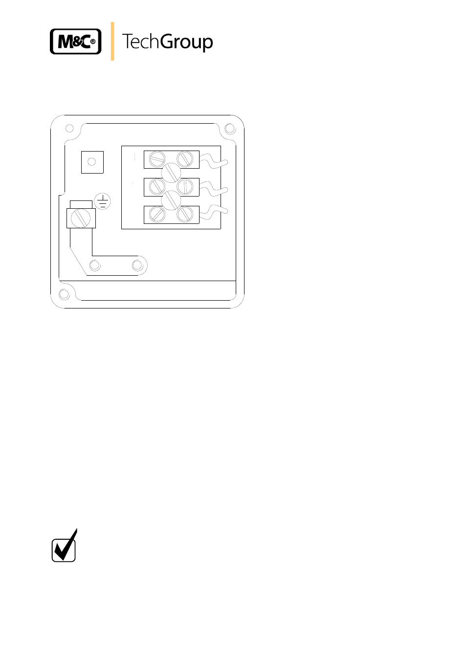
Figure 8 Electrical connection of the pump
Unscrew the cover of the connection box with the PG cable glands;
Put the cable through the cable gland and connect it according to figure 8; Connections are
marked in the connection box.
14.3
PNEUMATIC
Remove the protection plugs from the port threads (thread size G1/4”).
Accessories like hose connections are screwed into the port threads by sealing tape (using
M&C connectors sealing tape is not necessary).
Connect the suction and pressure lines.
Arrange the suction and pressure lines so that condensate cannot run into the pump.
N O T E !
The pump must only be used in the conditions specified in the technical
data. The pump should be installed away from heat sources and freely venti-
lated to prevent any accumulation of heat. For outdoor installation, the pump
must be installed in a housing protected from frost in the winter and suffi-
ciently ventilated in summer. Exposure to direct sunlight must be avoided.