Figure 2, Electricel connection of the filter fss-../h350 – M&C TechGroup FSS-..._H350 Operator's manual User Manual
Page 10
10
Gas sampling and gas conditioning technology
5-2.1.5-ME
W A R N I N G !
When connecting the equipment, please ensure that the supply
voltage is identical with the information provided on the model type
plate!
N O T E !
Attention must be paid to the requirements of IEC 364 (DIN VDE
0100) when setting high-power electrical units with nominal
voltages of up to 1000 V, together with the associated standards
and stipulations.
In any case we recommend the use of temperature resistant cable !
A main switch and matching fuse must be provided externally!
The main circuit must be equipped with a fuse corresponding to
the nominal current (over current protection); for electrical details
see technical data.
It is recommended to use the low temperature alarm. In case of an
alarm the flow can be stopped and the components downstream
the filter are safe from demage.
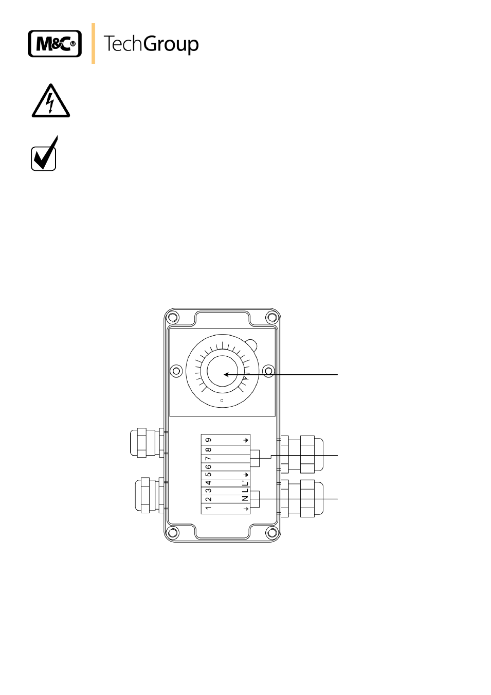
Figure 2 Electrical connection of the filter FSS-../H350
Remove the lid of the junction box. The electrical connection layout is located in the lid also.
Insert the mains cable (min. 3 x 1.5 mm²) through the lower cable gland and connect to the
appropriate terminals.
Insert the signal cable through the upper cable gland and connect to the appropriate terminals.
Screw lid back on.
Thermostat
Alarm contact
Power
230V/50Hz
(115V/60Hz)