Description, Function, Figure 2 – M&C TechGroup ECM Series Operator's manual User Manual
Page 9: Ecm-2g, 9description, 10 function
9
Gas sampling and gas conditioning technology
3-3.0-ME
9
DESCRIPTION
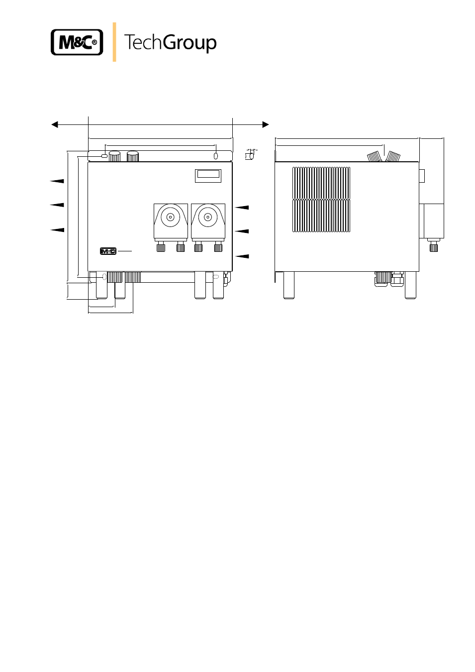
Figure 2 shows the ECM-2G cooler unit
.
Min. side distance
100
100
EC
M
Cooler
220
240
30
208
270
204
270
46
11
6
84
50
ventilation
opening
Compressor
ventilation outlet
Dimensions in mm
Figure 2 ECM-2G
The cooler ECM is equally suitable for wall installation. The depth of the housing of the cooler is
270mm (316mm with optional mounted peristaltic pumps ).
On the upper side of the cooler casing you will see the cutouts for 1 or 2 heat exchangers. Sample gas
enters and leaves the heat exchangers by the correspondingly connections on the upper part of the
heat exchangers (see 8. technical data).
The main power connector and the contact output for the status alarm can be connected at terminals
X1 respectively X3 located behind the removable front panel of the ECM housing.
At the bottom of the housing the following connections are provided as standard:
standard condensate outlets from the heat exchangers,
cable bushings 2 x M20 x 1,5 clamp range 6-12mm;
With under- respectively ambient pressure the condensate removal happens via the peristaltic pumps
SR25.2 optionally implemented in the cooler housing or externally with collecting vessels type
TG.../TK... . With over-pressure an automatic liquid drainer type AD-... is suitable.
10
FUNCTION
The M&C gas cooler type ECM is a compressor cooler with status alarm capability. This ensures
100% availability of the cooler.