Reception and storage, Figure 3, Schematic diagram of the heat exchanger function – M&C TechGroup ECM Series Operator's manual User Manual
Page 10
10
Gas sampling and gas conditioning technology
3-3.0-ME
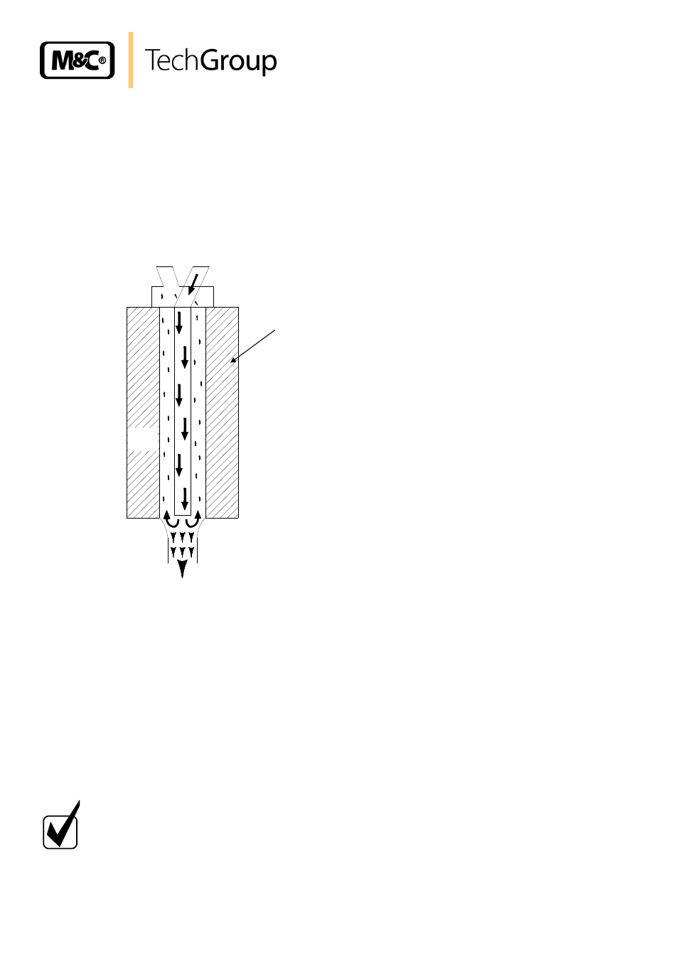
Up to 2 Jet-stream heat exchangers made of Borosilicate glass, PVDF or stainless steel are located in
a heat-insulated cooling block. All the heat exchangers are easily accessible and are arranged in such
a way that they can be removed very simply.
Figure 3 shows a schematic diagram of the functioning of the heat exchanger: The compressor cooler
system has a heat-insulated cooling block at a constant temperature of +5°C. The novel construction
of the heat exchanger guarantees a very good pre-separation of condensate and for that reason an
optimal drying of sample gas.
+5°C
Sample
OUT
Sample
IN
Condensate OUT
Cooling
block
Figure 3 Schematic diagram of the heat exchanger function
11
RECEPTION AND STORAGE
The ECM gas cooler is a complete pre-installed unit.
Carefully inspect the ECM and any special accessories included with it immediately on arrival
by removing them from the packing and checking for missing articles against the packing list !
Check the items for any damage in transit and, if required, inform the shipping insurance
company immediately of the damage found!
N O T E !
The cooler must be stored in a weather protected frost-free area!
During transport and when in storage, the cooler must always be stood up
with the transport feet positioned underneath so that the oil in the closed
compressor circuit cannot run out of this compressor case.
If the cooler is transported on its back by mistake, it must stood in the
operating position for approx. 24 hours before it is switched on!