Electrical connection, Signal output, Option alarm contact output – M&C TechGroup PMA 10S Operator's manual User Manual
Page 16: Figure 6, Plug connection signal output
16
Gas sampling and gas conditioning technology
9-1.1-ME
14
ELECTRICAL CONNECTION
W A R N I N G !
False supply voltage can damage the equipment. When connec t-
ing the equipment, please ensure that the supply voltage is
identical with the information provided on the model type plate!
At the rear side there is the low heat device socket. A 2m connection cable with low heat device
connector and earthing type plug is included in the scope of delivery.
14.1
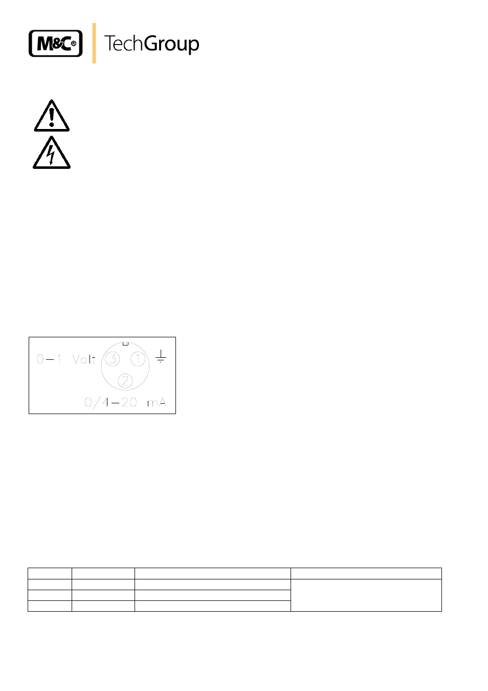
SIGNAL OUTPUT
The PMA 10(S) has a signal output of 0
– 1V as standard, that is available in the chosen measur-
ing range at the 3-pole bushing in the front of the analyser ( Pin 1/- und 3/+).
With option mA-output, additionally a signal of 0 - 20 mA or 4 - 20 mA is available at the 3-pole
bushing in the front of the analyser ( Pin 1/- und 2/+).
The output signals are not galvanically isolated.
For the connection of the signal output an adequate plug is provided.
Figure 6
Plug connection signal output
14.2
OPTION ALARM CONTACT OUTPUT
The alarm contact output is designed as MIN- as well as MAX-contact. Ex works the analyser is
delivered with a MAX-contact.
If a MIN-contact is favoured, the 4 screws of the front panel have to be removed and the switch
S2 on the alarm-board has to be switched. For output a relais contact (change over contact) and
optionally a buzzer is available. The intermitting buzzer switches off after 30 seconds automat i-
cally or has a manual reset as option. The relais contact is lead to a female plug at the rear side.
A corresponding plug with the following assignment is included in the s cope of delivery (see also
Fig. 7) :
Contact Assignment Explanation
Contact rating
1
mc
Tie point
max. 2A
max. 24V
DC
/100V
AC
2
nc
Normally closed
3
no
Normally open