3d slsm configurations, Assignment principles, Available slsm 2x configurations – EVS XTnano Version 11.01 - November 2012 Configuration Manual User Manual
Page 76
3.2.7.
3D SLSM Configurations
Assignment Principles
Note
The 3D Dual Link SLSM configurations are only available on an XTnano server
equipped with V3X boards.
The combination of 3D standards and SLSM configurations associates the following
individual rules for connector assignments on the rear panel:
•
For 3D in Dual Link with V3X boards, the primary link of a codec module is used for
the first connector, and the secondary link for the same codec module is used for the
second connector.
•
For the SLSM 2 Phase configurations, one SLSM recorder accounts for one logical
channel, but corresponds to two physical channels. This means that the primary
connectors of two codec modules will be used for one SLSM 2 Phase recorder.
•
For the SLSM 3 Phase configurations, one SLSM recorder accounts for one logical
channel, but corresponds to three physical channels. This means that the primary
connectors of three codec modules will be used for one SLSM 3 Phase recorder.
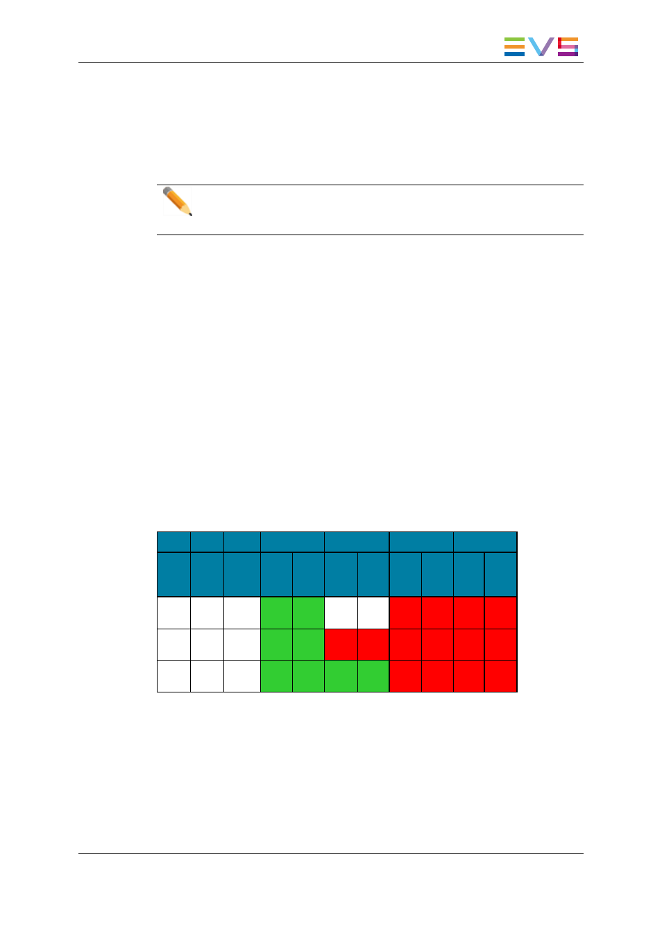
Available SLSM 2x Configurations
The table below shows the available 3D configurations with SLSM 2 Phase cameras on
an XTnano server. The table shows the link assignment at the level of the codec module
of a V3X board.
IN4/OUT1
IN3/OUT2
IN2/OUT3
IN1/OUT4
#REC
SLSM
2x
#REC
#PLAY
Prim.
Link
Sec.
Link
Prim.
Link
Sec.
Link
Prim.
Link
Sec.
Link
Prim.
Link
Sec.
Link
1
0
1
PLAY
1A
PLAY
1B
REC
1,2A
REC
1,2B
REC
1,1A
REC
1,1B
1
1
1
PLAY
1A
PLAY
1B
REC
2A
REC
2B
REC
1,2A
REC
1,2B
REC
1,1A
REC
1,1B
1
0
2
PLAY
1A
PLAY
1B
PLAY
2A
PLAY
2B
REC
1,2A
REC
1,2B
REC
1,1A
REC
1,1B
XTnano Server - Version 11.01 - Configuration Manual
3. Multicam Configuration
66