3 leds – ZyXEL Communications XGS-4526 User Manual
Page 40
Chapter 3 Hardware Overview
XGS-4526 User’s Guide
40
• VT100 terminal emulation
• 9600 bps
• No parity, 8 data bits, 1 stop bit
• No flow control
Connect the male 9-pin end of the RS-232 console cable to the console port of the
Switch. Connect the female end to a serial port (COM1, COM2 or other COM port)
of your computer.
3.3 LEDs
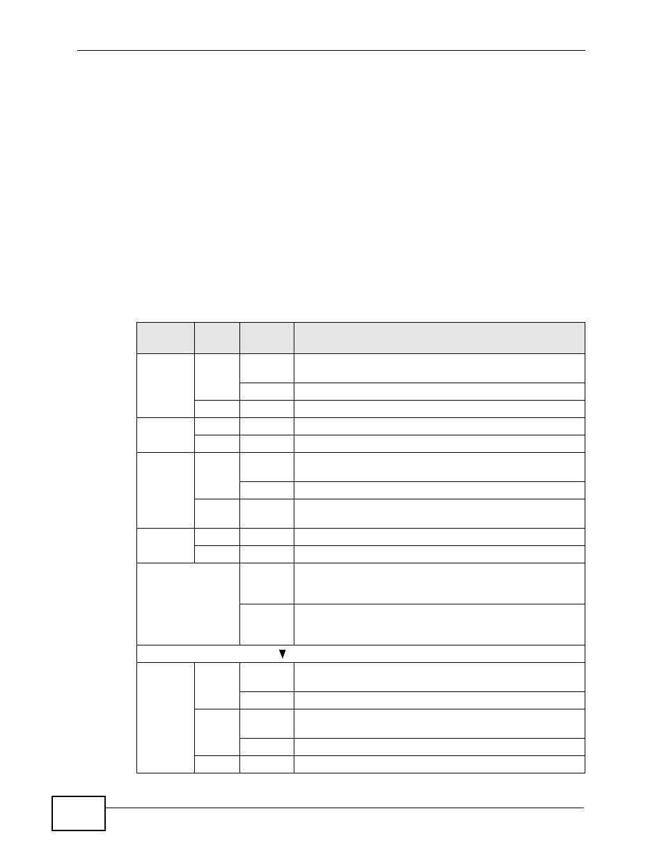
The following table describes the LEDs.
Table 3 LEDs
LED
COLO
R
STATUS
DESCRIPTION
BPS
Green
Blinking
The system is receiving power from the backup power
supply.
On
The backup power supply is connected and active.
Off
The backup power supply is not ready or not active.
PWR
Green
On
The system is turned on.
Off
The system is off.
SYS
Green
Blinking
The system is rebooting and performing self-diagnostic
tests.
On
The system is on and functioning properly.
Off
The power is off or the system is not ready/
malfunctioning.
ALM
Red
On
There is a hardware failure.
Off
The system is functioning normally.
System Status
Displays
hourglas
s icon
The Switch is starting up.
Displays
Stack ID
number
The LED is showing the Stack ID number of the Switch.
1000Base-T Gigabit Ports ( )
1-24
Green
Blinking
The system is transmitting/receiving to/from a 10/1000
Mbps Ethernet network.
On
The link to a 10/1000 Mbps Ethernet network is up.
Amber
Blinking
The system is transmitting/receiving to/from a 100 Mbps
Ethernet network.
On
The link to a 100 Mbps Ethernet network is up.
Off
The link to an Ethernet network is down.