2 rear panel – ZyXEL Communications XGS-4526 User Manual
Page 38
Chapter 3 Hardware Overview
XGS-4526 User’s Guide
38
2
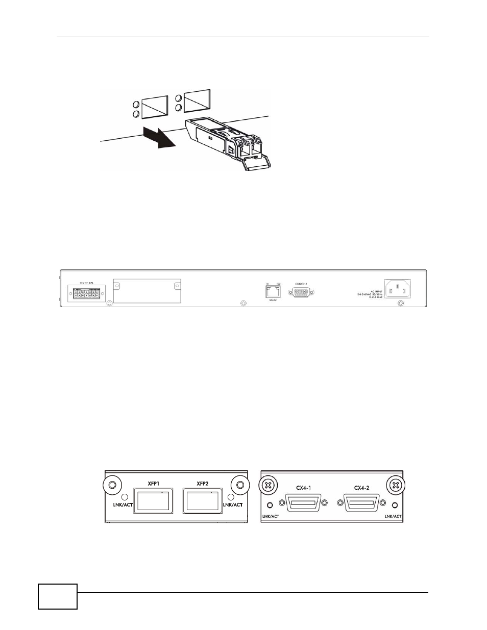
Pull the transceiver out of the slot.
Figure 12 Transceiver Removal Example
3.2 Rear Panel
The following figure shows the rear panel of the Switch.
Figure 13 Rear Panel
The rear panels contain:
• A connector for the backup power supply (A)
• An optional slot (B) for installing an EM-422 or EM-412 uplink module
• An RJ-45 out-of-band management port (C)
• An RS-232 management console port (D)
• A connector for the power receptacle (E)
The following figure shows the front panel of the EM-422 and EM-412 modules.
Figure 14 The Front Panel of the EM-422 and EM-412 Modules
B
D
E
A
C
EM-412
EM-422
See also other documents in the category ZyXEL Communications Computer Accessories:
- ZyXEL Dimension GS-1116A (30 pages)
- ZyXEL Dimension ES-2108PWR (4 pages)
- DIMENSION ES-4024 (4 pages)
- MI-7526F (6 pages)
- ZyXEL Dimension ES-2048 (306 pages)
- DIMENSION ES-1016A (2 pages)
- ONU-6040B-21 (19 pages)
- HOMEBOUND TRIPLE PLAY DELIVERY ES-315-F (2 pages)
- IES-708-22 (6 pages)
- Version 1.03 (242 pages)
- ZyXEL Dimension ES-1552 (43 pages)
- ES-2108 (224 pages)
- ZyXEL Dimension ES-1124 (48 pages)
- 2-Slot 10GBase-CX4 10Gigabit Module EM-412 (18 pages)
- GS-105B/108B (48 pages)
- ES-4024A (128 pages)
- ETHERNET SWITCHES ES-1016 (2 pages)
- GS-4012F/4024 (363 pages)
- ZyXEL Dimension ES-2024 (195 pages)
- ZyXEL Dimension ES-2108 (277 pages)
- ZyXEL Dimension GS-3012F (237 pages)
- VES-1000 (155 pages)
- PoE-80 (23 pages)
- ES-1124 (30 pages)
- 4500 Series (7 pages)
- ES-3148 Series (362 pages)
- GS-3012F Series (300 pages)
- Ethernet-to-Fiber Media Converter MC1000-SFP-FP (34 pages)
- GS2200-24P (4 pages)
- ES-105A/108A (2 pages)
- ZyXEL Dimension GS-1016 (32 pages)
- EES-1024AF (99 pages)
- GS-4012 (462 pages)
- IES-6000 (100 pages)
- ES-315 (166 pages)
- ES-2108 Series (283 pages)
- ZyXEL Dimension ES-2024PWR (286 pages)
- GS-3012F/3012 (314 pages)
- GS-108B (48 pages)
- GS-105 (7 pages)
- GS-4012F (462 pages)
- VES-1616 (118 pages)
- A-6000 (23 pages)
- LAYER 3 ES-3124 (337 pages)
- GS-105A (2 pages)