15 low-power mode wakeup timing – Texas Instruments Digital Signal Processor SM320F2812-HT User Manual
Page 99
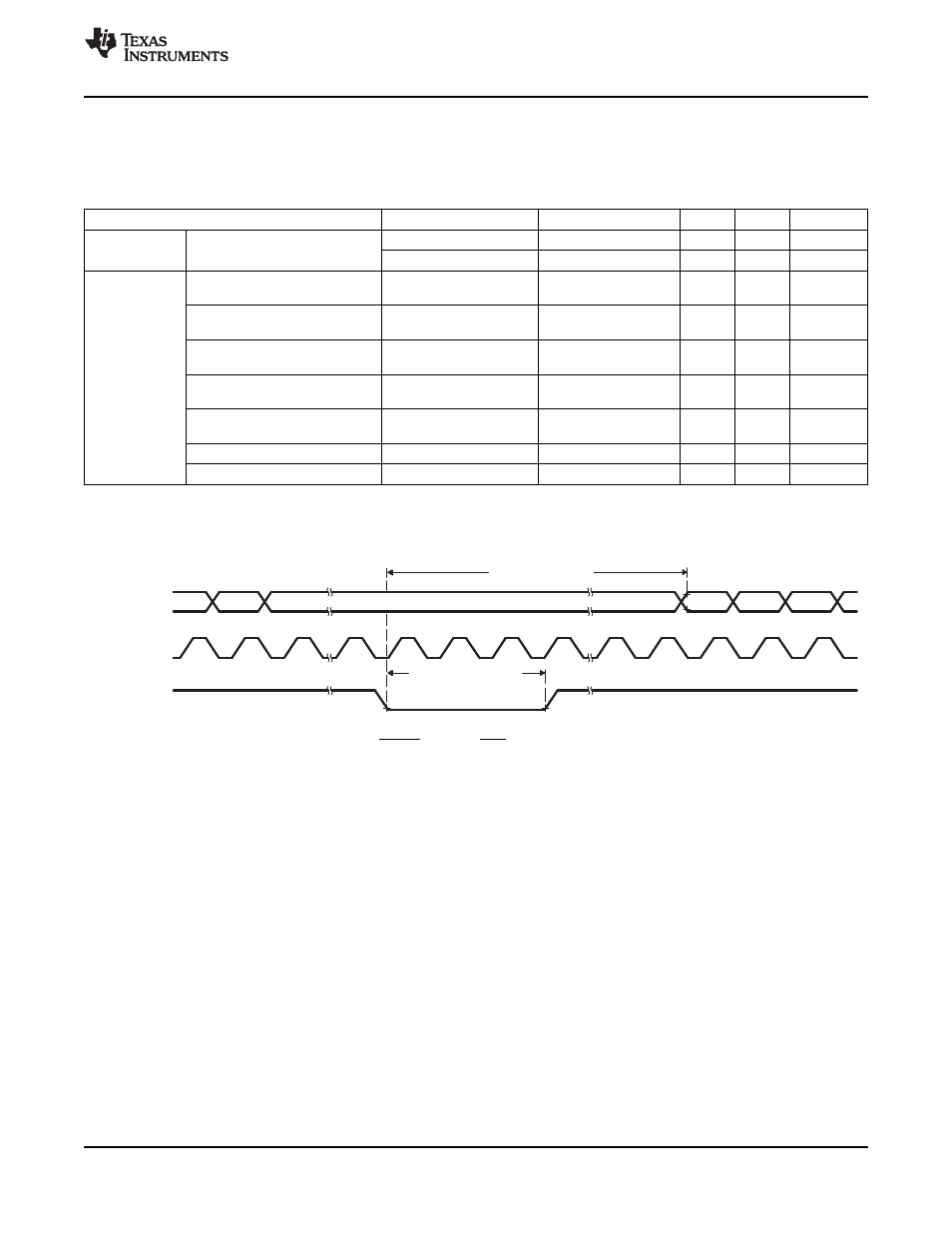
WAKE INT
(see Note B)
XCLKOUT
(see Note A)
A0−A15
t
d(WAKE−IDLE)
t
w(WAKE−INT)
SGUS062B
–
JUNE 2009
–
REVISED JUNE 2011
6.15 Low-Power Mode Wakeup Timing
is also the IDLE Mode Wake-Up Timing Requirements table.
Table 6-10. IDLE Mode Switching Characteristics
(1)
PARAMETER
TEST CONDITIONS
MIN
TYP
MAX
UNIT
Without input qualifier
2 x t
c(SCO)
Cycles
Pulse duration, external wake-up
t
w(WAKE-INT)
signal
With input qualifier
1
×
t
c(SCO)
+ IQT
(2)
Cycles
Delay time, external wake signal
to program execution resume
(3)
–
Wake-up from Flash
Without input qualifier
8
×
t
c(SCO)
Cycles
–
Flash module in active state
–
Wake-up from Flash
With input qualifier
8
×
t
c(SCO)
+ IQT
(2)
Cycles
–
Flash module in active state
t
d(WAKE-IDLE)
–
Wake-up from Flash
Without input qualifier
1050
×
t
c(SCO)
Cycles
–
Flash module in sleep state
–
Wake-up from Flash
With input qualifier
1050
×
t
c(SCO)
+ IQT
(2)
Cycles
–
Flash module in sleep state
–
Wake-up from SARAM
Without input qualifier
8
×
t
c(SCO)
Cycles
–
Wake-up from SARAM
With input qualifier
8
×
t
c(SCO)
+ IQT
(2)
Cycles
(1)
Not production tested.
(2)
Input Qualification Time (IQT) = [5
×
QUALPRD
Ч
2]
Ч
t
c(SCO)
(3)
This is the time taken to begin execution of the instruction that immediately follows the IDLE instruction. Execution of an ISR (triggered
by the wake-up) signal involves additional latency.
A.
XCLKOUT = SYSCLKOUT
B.
WAKE INT can be any enabled interrupt, WDINT, XNMI, or XRS.
Figure 6-13. IDLE Entry and Exit Timing
Copyright
©
2009
–
2011, Texas Instruments Incorporated
Electrical Specifications
99
Product Folder Link(s):